The Conversation (1)

There's no planned mission to send a lander to Europa, but this artist's rendition gives a sense of what one such lander might look like, including the new antenna design necessary for staying in touch with Earth.
Marek Denko/Noemotion
DarkGray
Europa, one of Jupiter's Galilean moons, has twice as much liquid water as Earth's oceans, if not more. An ocean estimated to be anywhere from 40 to 100 miles (60 to 150 kilometers) deep spans the entire moon, locked beneath an icy surface over a dozen kilometers thick. The only direct evidence for this ocean is the plumes of water that occasionally erupt through cracks in the ice, jetting as high as 200 km above the surface.
The endless, sunless, roiling ocean of Europa might sound astoundingly bleak. Yet it's one of the most promising candidates for finding extraterrestrial life. Designing a robotic lander that can survive such harsh conditions will require rethinking all of its systems to some extent, including arguably its most important: communications. After all, even if the rest of the lander works flawlessly, if the radio or antenna breaks, the lander is lost forever.
Ultimately, when NASA's Jet Propulsion Laboratory (JPL), where I am a senior antenna engineer, began to seriously consider a Europa lander mission, we realized that the antenna was the limiting factor. The antenna needs to maintain a direct-to-Earth link across more than 550 million miles (900 million km) when Earth and Jupiter are at their point of greatest separation. The antenna must be radiation-hardened enough to survive an onslaught of ionizing particles from Jupiter, and it cannot be so heavy or so large that it would imperil the lander during takeoff and landing. One colleague, when we laid out the challenge in front of us, called it impossible. We built such an antenna anyway—and although it was designed for Europa, it is a revolutionary enough design that we're already successfully implementing it in future missions for other destinations in the solar system.
Currently, the only planned mission to Europa is the Clipper orbiter, a NASA mission that will study the moon's chemistry and geology and will likely launch in 2024. Clipper will also conduct reconnaissance for a potential later mission to put a lander on Europa. At this time, any such lander is conceptual. NASA has still funded a Europa lander concept, however, because there are crucial new technologies that we need to develop for any successful mission on the icy world. Europa is unlike anywhere else we've attempted to land before.
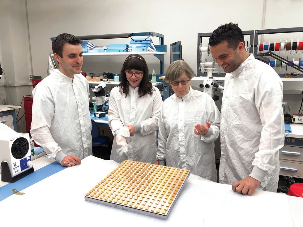 The antenna team, including the author (right), examine one of the antenna's subarrays. Each golden square is a unit cell in the antenna.JPL-Caltech/NASA
For context, so far the only lander to explore the outer solar system is the European Space Agency's Huygens lander. It successfully descended to Saturn's moon Titan in 2005 after being carried by the Cassini orbiter. Much of our frame of reference for designing landers—and their antennas—comes from Mars landers.
Traditionally, landers (and rovers) designed for Mars missions rely on relay orbiters with high data rates to get scientific data back to Earth in a timely manner. These orbiters, such as the Mars Reconnaissance Orbiter and Mars Odyssey, have large, parabolic antennas that use large amounts of power, on the order of 100 watts, to communicate with Earth. While the Perseverance and Curiosity rovers also have direct-to-Earth antennas, they are small, use less power (about 25 W), and are not very efficient. These antennas are mostly used for transmitting the rover's status and other low-data updates. These existing direct-to-Earth antennas simply aren't up to the task of communicating all the way from Europa.
Additionally, Europa, unlike Mars, has virtually no atmosphere, so landers can't use parachutes or air resistance to slow down. Instead, the lander will depend entirely on rockets to brake and land safely. This necessity limits how big it can be—too heavy and it will require far too much fuel to both launch and land. A modestly sized 400-kilogram lander, for example, requires a rocket and fuel that combined weigh between 10 to 15 tonnes. The lander then needs to survive six or seven years of deep space travel before finally landing and operating within the intense radiation produced by Jupiter's powerful magnetic field.
We also can't assume a Europa lander would have an orbiter overhead to relay signals, because adding an orbiter could very easily make the mission too expensive. Even if Clipper is miraculously still functional by the time a lander arrives, we won't assume that will be the case, as the lander would arrive well after Clipper's official end-of-mission date.
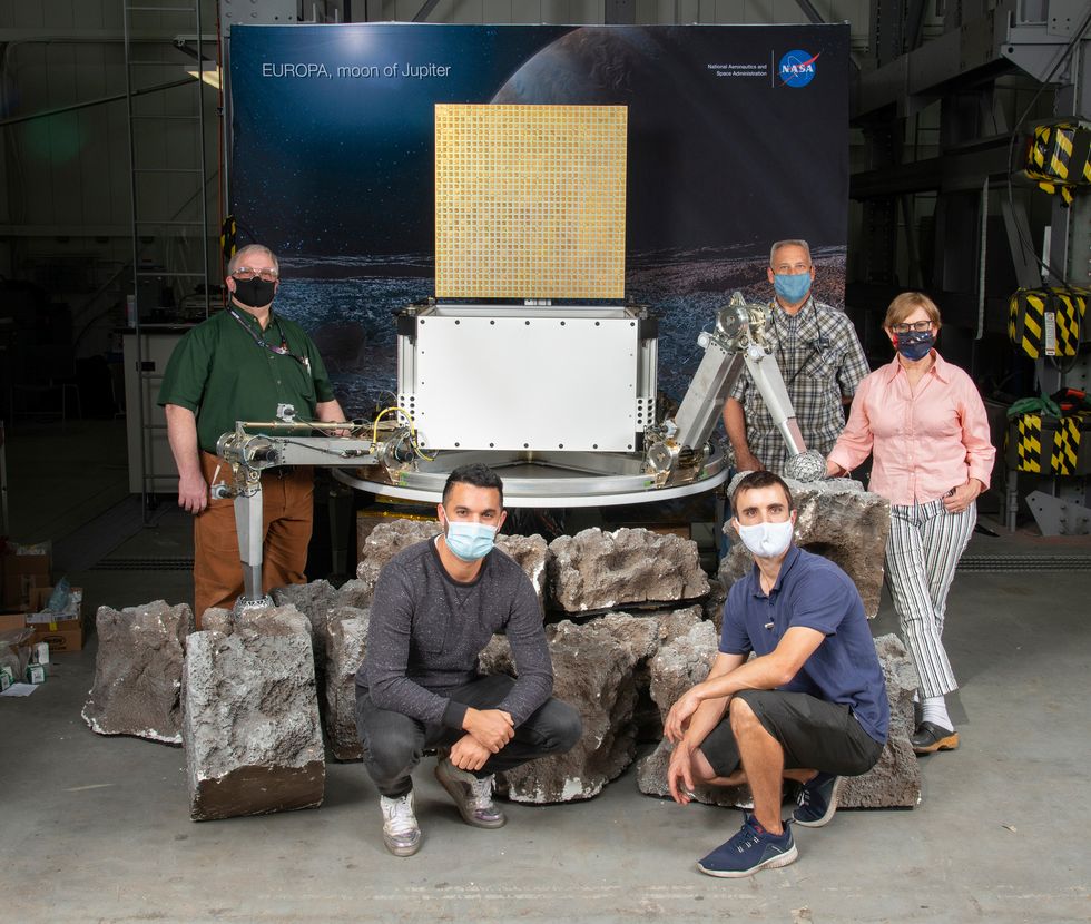 JPL engineers, including the author (bottom row on left), pose with a mock-up of a Europa lander concept. The model includes several necessary technological developments, including the antenna on top and legs that can handle uneven terrain.JPL-Caltech/NASA
I've mentioned previously that the antenna will need to transmit signals up to 900 million km. As a general rule, less efficient antennas need a larger surface area to transmit farther. But as the lander won't have an orbiter overhead with a large relay antenna, and it won't be big enough itself for a large antenna, it needs a small antenna with a transmission efficiency of 80 percent or higher—much more efficient than most space-bound antennas.
So, to reiterate the challenge: The antenna cannot be large, because then the lander will be too heavy. It cannot be inefficient for the same reason, because requiring more power would necessitate bulky power systems instead. And it needs to survive exposure to a brutal amount of radiation from Jupiter. This last point requires that the antenna must be mostly, if not entirely, made out of metal, because metals are more resistant to ionizing radiation.
The antenna we ultimately developed depends on a key innovation: The antenna is made up of circularly polarized, aluminum-only unit cells—more on this in a moment—that can each send and receive on X-band frequencies (specifically, 7.145 to 7.19 gigahertz for the uplink and 8.4 to 8.45 GHz for the downlink). The entire antenna is an array of these unit cells, 32 on a side or 1,024 in total. The antenna is 32.5 by 32.5 inches (82.5 by 82.5 centimeters), allowing it to fit on top of a modestly sized lander, and it can achieve a downlink rate to Earth of 33 kilobits per second at 80 percent efficiency.
Let's take a closer look at the unit cells I mentioned, to better understand how this antenna does what it does. Circular polarization is commonly used for space communications. You might be more familiar with linear polarization, which is often used for terrestrial wireless signals; you can imagine such a signal propagating across a distance as a 2D sine wave that's oriented, say, vertically or horizontally relative to the ground. Circular polarization instead propagates as a 3D helix. This helix pattern makes circular polarization useful for deep space communications because the helix's larger “cross section" doesn't require that the transmitter and receiver be as precisely aligned. As you can imagine, a superprecise alignment across almost 750 million km is all but impossible. Circular polarization has the added benefit of being less sensitive to Earth's weather when it arrives. Rain, for example, causes linearly polarized signals to attenuate more quickly than circularly polarized ones.
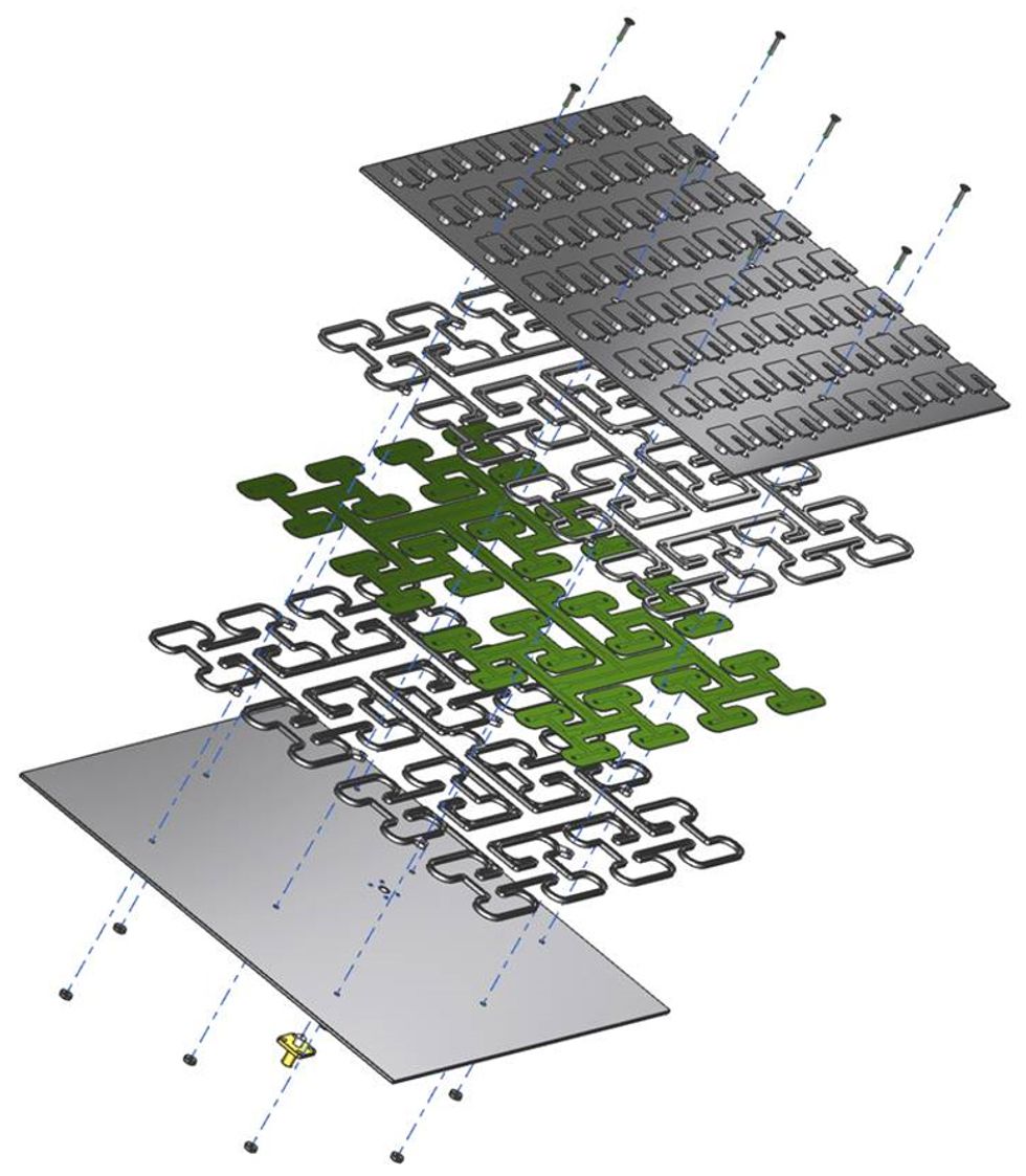 This exploded view of an 8-by-8 subarray of the antenna shows the unit cells (top layer) that work together to create steerable signal beams, and the three layers of the power divider sandwiched between the antenna's casing.JPL-Caltech/NASA
Each unit cell, as mentioned, is entirely made of aluminum. Earlier antenna arrays that similarly use smaller component cells include dielectric materials like ceramic or glass to act as insulators. Unfortunately, dielectric materials are also vulnerable to Jupiter's ionizing radiation. The radiation builds up a charge on the materials over time, and precisely because they're insulators there's nowhere for that charge to go—until it's ultimately released in a hardware-damaging electrostatic discharge. So we can't use them.
As mentioned before, metals are more resilient to ionizing radiation. The problem is they're not insulators, and so an antenna constructed entirely out of metal is still at risk of an electrostatic discharge damaging its components. We worked around this problem by designing each unit cell to be fed at a single point. The “feed" is the connection between an antenna and the radio's transmitter and receiver. Typically, circularly polarized antennas require two perpendicular feeds to control the signal generation. But with a bit of careful engineering and the use of a type of automated optimization called a genetic algorithm, we developed a precisely shaped single feed that could get the job done. Meanwhile, a comparatively large metal post acts as a ground to protect each feed from electrostatic discharges.
The unit cells are placed in small 8-by-8 subarrays, 16 subarrays in total. Each of these subarrays is fed with something we call a suspended air stripline, in which the transmission line is suspended between two ground planes, turning the gap in between into a dielectric insulator. We can then safely transmit power through the stripline while still protecting the line from electric discharges that would build up on a dielectric like ceramic or glass. Additionally, suspended air striplines are low loss, which is perfect for the highly efficient antenna design we wanted.
Put together, the new antenna design accomplishes three things: It's highly efficient, it can handle a large amount of power, and it's not very sensitive to temperature fluctuations. Removing traditional dielectric materials in favor of air striplines and an aluminum-only design gives us high efficiency. It's also a phased array, which means it uses a cluster of smaller antennas to create steerable, tightly focused signals. The nature of such an array is that each individual cell needs to handle only a fraction of the total transmission power. So while each individual cell can handle only a few watts, each subarray can handle more than 100 watts. And finally, because the antenna is made of metal, it expands and contracts uniformly as the temperature changes. In fact, one of the reasons we picked aluminum is because the metal does not expand or contract much as temperatures change.
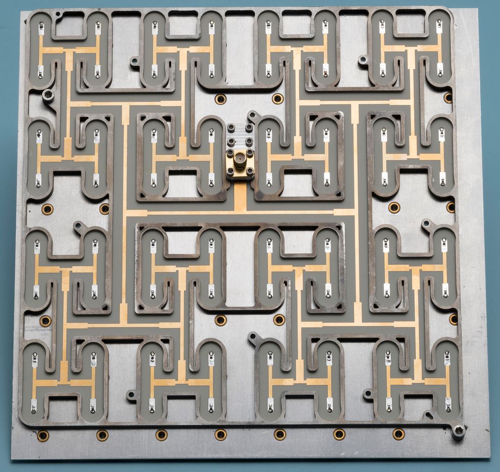 The power divider for an 8-by-8 subarray splits the signal power into a fraction that each unit cell can tolerate without being damaged.JPL-Caltech/NASA
When I originally proposed this antenna concept to the Europa lander project, I was met with skepticism. Space exploration is typically a very risk-averse endeavor, for good reason—the missions are expensive, and a single mistake can end one prematurely. For this reason, new technologies may be dismissed in favor of tried-and-true methods. But this situation was different because without a new antenna design, there would never be a Europa mission. The rest of my team and I were given the green light to prove the antenna could work.
Designing, fabricating, and testing the antenna took only 6 months. To put that in context, the typical development cycle for a new space technology is measured in years. The results were outstanding. Our antenna achieved the 80 percent efficiency threshold on both the send and receive frequency bands, despite being smaller and lighter than other antennas.
In order to prove how successful our antenna could be, we subjected it to a battery of extreme environmental tests, including a handful of tests specific to Europa's atypical environment.
One test is what we call thermal cycling. For this test, we place the antenna in a room called a thermal chamber and adjust the temperature over a large range—as low as –170 ℃ and as high as 150 ℃. We put the antenna through multiple temperature cycles, measuring its transmitting capabilities before, during, and after each cycle. The antenna passed this test without any issues.
 Each unit cell is pure aluminum. Collectively, they create a steerable signal by canceling out one another's signals in unwanted directions and reinforcing the signal in the desired direction.JPL-Caltech/NASA
The antenna also needed to demonstrate, like any piece of hardware that goes into space, resilience against vibrations. Rockets—and everything they're carrying into space—shake intensely during launch, which means we need to be sure that anything that goes up doesn't come apart on the trip. For the vibration test, we loaded the entire antenna onto a vibrating table. We used accelerometers at different locations on the antenna to determine if it was holding up or breaking apart under the vibrations. Over the course of the test, we ramped up the vibrations to the point where they approximate a launch.
Thermal cycling and vibration tests are standard tests for the hardware on any spacecraft, but as I mentioned, Europa's challenging environment required a few additional nonstandard tests. We typically do some tests in anechoic chambers for antennas. You may recognize anechoic chambers as those rooms with wedge-covered surfaces to absorb any signal reflections. An anechoic chamber makes it possible for us to determine the antenna's signal propagation over extremely long distances by eliminating interference from local reflections. One way to think about it is that the anechoic chamber simulates a wide open space, so we can measure the signal's propagation and extrapolate how it will look over a longer distance.
What made this particular anechoic chamber test interesting is that it was also conducted at ultralow temperatures. We couldn't make the entire chamber that cold, so we instead placed the antenna in a sealed foam box. The foam is transparent to the antenna's radio transmissions, so from the point of view of the actual test, it wasn't there. But by connecting the foam box to a heat exchange plate filled with liquid nitrogen, we could lower the temperature inside it to –170 ℃. To our delight, we found that the antenna had robust long-range signal propagation even at that frigid temperature.
The last unusual test for this antenna was to bombard it with electrons in order to simulate Jupiter's intense radiation. We used JPL's Dynamitron electron accelerator to subject the antenna to the entire ionizing radiation dose the antenna would see during its lifetime in a shortened time frame. In other words, in the span of two days in the accelerator, the antenna was exposed to the same amount of radiation as it would be during the six- or seven-year trip to Europa, plus up to 40 days on the surface. Like the anechoic chamber testing, we also conducted this test at cryogenic temperatures that were as close to those of Europa's surface conditions as possible.
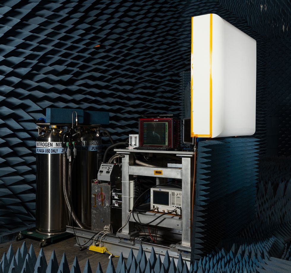 The antenna had to pass signal tests at cryogenic temperatures (–170 °C) to confirm that it would work as expected on Europa's frigid surface. Because it wasn't possible to bring the temperature of the entire anechoic chamber to cryogenic levels, the antenna was sealed in a white foam box.JPL-Caltech/NASA
The reason for the electron bombardment test was our concern that Jupiter's ionizing radiation would cause a dangerous electrostatic discharge at the antenna's port, where it connects to the rest of the lander's communications hardware. Theoretically, the danger of such a discharge grows as the antenna spends more time exposed to ionizing radiation. If a discharge happens, it could damage not just the antenna but also hardware deeper in the communications system and possibly elsewhere in the lander. Thankfully, we didn't measure any discharges during our test, which confirms that the antenna can survive both the trip to and work on Europa.
We designed and tested this antenna for Europa, but we believe it can be used for missions elsewhere in the solar system. We're already tweaking the design for the joint JPL/ESA Mars Sample Return mission that—as the name implies—will bring Martian rocks, soil, and atmospheric samples back to Earth. The mission is currently slated to launch in 2026. We see no reason why our antenna design couldn't be used on every future Mars lander or rover as a more robust alternative—one that could also increase data rates 4 to 16 times those of current antenna designs. We also could use it on future moon missions to provide high data rates.
Although there isn't an approved Europa lander mission yet, we at JPL will be ready if and when it happens. Other engineers have pursued different projects that are also necessary for such a mission. For example, some have developed a new, multilegged landing system to touch down safely on uncertain or unstable surfaces. Others have created a “belly pan" that will protect vulnerable hardware from Europa's cold. Still others have worked on an intelligent landing system, radiation-tolerant batteries, and more. But the antenna remains perhaps the most vital system, because without it there will be no way for the lander to communicate how well any of these other systems are working. Without a working antenna, the lander will never be able to tell us whether we could have living neighbors on Europa.
This article appears in the August 2021 print issue as “An Antenna Made for an Icy, Radioactive Hell."
During the editorial process some errors were introduced to this article and have been corrected on 27 July 2021. We originally misstated the amount of power used by Mars orbiters and the Europa antenna design, as well as the number of unit cells in each subarray. We also incorrectly suggested that the Europa antenna design would not require a gimbal or need to reorient itself in order to stay in contact with Earth.