My home of Port Townsend in Washington is a community full of arty types and makers. Calls to participate in local cultural activities are not uncommon, but when I saw one for a pinhole-camera photography contest it caught my eye. I’d played with pinhole cameras many years ago, and I wondered if the electrotech skills I’d accumulated since then could be used to improve upon the traditional pinhole camera, while retaining its unique characteristics. Could I make a digital pinhole camera?
Optically speaking, pinholes have some compelling characteristics that lenses can’t match. For one, a pinhole camera has an effectively infinite depth of field: everything in its field of view is in focus, regardless of how near or far any object is. And there are no distortions, such as chromatic aberration, that are produced by lenses. Recent years have seen an increase in interest in pinhole photography, with a variety of cameras being sold commercially and international photography events.
On the downside, both off-the-shelf and DIY pinhole cameras use film or photographic paper. The cost of buying and developing film quickly adds up, and of course there’s a long delay between taking a photo and seeing the results. Perhaps most significantly, taking photos with a film-based pinhole camera requires long exposure times—typically several seconds even in bright sunlight—increasing the chance of a shot being ruined by unwanted motion.
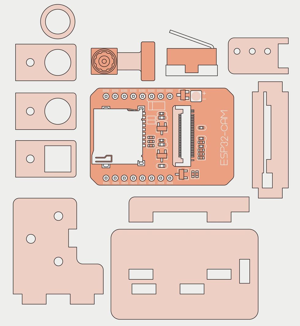 The frame and pinhole lens attachments are made from laser-cut pieces of wood. These hold the microcontroller board [center], image sensor, and the microswitch that acts as a shutter control [top center].James Provost
My hunch was that using a digital sensor would solve both these problems. I had a US $10 ESP32-Cam board left over from a previous project that I realized would be perfect for this endeavor. The board integrates the popular Wi-Fi–enabled ESP32 microcontroller with a microSD card socket, an indicator LED, and an interface for a number of low-cost image sensors. I used an OV2460 camera module, which can support a maximum resolution of 1,600 by 1,200 pixels when used with the ESP32-CAM. I removed the OV2460’s lens to expose the image sensor.
I wired up a microswitch to one of the board’s general-purpose input/output pins and wrote some firmware to use the switch as a shutter control and save images to the microSD card. I also programmed the indictor LED to blink out some error codes in case something went wrong, such as trying to write to a full microSD card. Writing this glue code didn’t take long, thanks to the large number of software libraries available for the ESP32-CAM.
I made a wooden case to hold the sensor, ESP32-CAM board, and the shutter switch using my Glowforge laser cutter. The critical pinhole assembly can be detached, allowing me to adjust the focal length—and hence the field of view of the camera—by swapping out different assemblies. This brings the flexibility of detachable lenses to pinhole photography, another nice bonus!
However, nothing comes for free. Pinholes do vary in size, and the trade-off for all these digital advantages is that you have to fabricate a camera pinhole with a smaller diameter than you can get away with in a traditional pinhole camera. This is because the sensor is much smaller than a frame of film: 4 millimeters wide for the sensor versus, say, 35 or 120 mm for film. Consequently, to ensure the complete image created by the pinhole falls onto the sensor’s surface, the sensor must be much closer to the pinhole than with film. When you calculate the optics needed for that arrangement, the result is a smaller hole.
If I was mass-producing this camera, the go-to process would be chemical etching. Once you dial in all the parameters you can precisely make very small holes all day long. But the time and effort involved in setting up an etching process meant I wanted to find another way.
My first solution was get a thin piece of brass and make a dent in it with a center punch. Then I sanded off the brass from the other side until I just broke through to the dent. This made a nice tiny little hole, but it was a lot of work, and I knew I’d want a few pinholes on hand as I tested the camera.
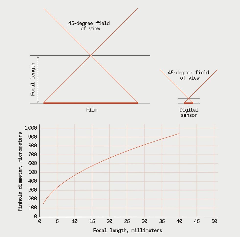 Not all pinholes are the same. Traditional pinhole cameras have relatively long focal lengths because of the size of a frame of film, allowing for larger and easier-to-make pinholes. Because digital sensors are much smaller, a shorter focal length is required, demanding in turn a much smaller pinhole.James Provost
So I went back to basics and tried stretching some aluminum foil and piercing it with a needle. Normally, this would result in a hole that is far too large. However, I discovered that if I put the foil down on the plastic surface of my work bench, and pressed the needle gently into the foil, the plastic would allow just the very tip of the needle to penetrate the foil. Although not tremendously reliable, this method lets me make a lot of pinholes quickly and check them to find the ones with the ideal diameter.
Then it was time to try out the camera, so I took it out to a local lighthouse and hooked up a battery. The sensitivity of the image sensor means that the exposure time required is only a fraction of second, and I was able to download my photos from the microSD card and check them right there on the shore. Yet the photos retained the luminous look that’s characteristic of traditional pinhole photography. Success!
An obvious improvement would be to coat the inside of the interchangeable optical assemblies with some matte black material, as internal reflections add some fuzziness to my photos. Another would be to add an LCD screen so that you could view exactly what the camera is seeing in real time—the ESP32 controller has more than enough spare compute power to drive a small display.
Meanwhile, I’m still waiting to hear how I did in that photography contest!
- The dawn of organic electronics ›
- Steve Mann: My “Augmediated” Life ›
- Light-Field Photography Revolutionizes Imaging ›
- Impossible Photo Feat Now Possible Via Holography - IEEE Spectrum ›