
When I was growing up, I remember reading in an electronics-for-young-folk book that good vision was a must-have if you wanted to build or design electronics: Even color blindness was a serious limitation. This was a myth. In fact, there's an active community of people with low or no vision who are using today's maker ecosystem to solve problems in their daily lives. And with some tweaks to the familiar symbols used in circuit diagrams, that community could grow even larger.
“The Arduino platform is actually wonderful for accessibility because we can create our own tools. We can create things that might be expensive on the market and customize them to our needs," says Chancey Fleet, the assistive technology coordinator at the Andrew Heiskell Braille and Talking Book Library in New York City. “There's specific techniques that we use for soldering and for getting around the board," says Fleet, giving the example of how some people use a Braille stylus to count pins as though it's “a tiny cane navigating the header." (For more details about how to work as a visually impaired maker, Fleet recommends the Blind Arduino Project.)
However, one big obstacle to introducing blind and low-vision people to electronics is circuit diagrams. Experienced builders can use written descriptions of a circuit, but beginners, in particular, benefit from the kind of spatial information provided by a schematic. This came home to Lauren Race when she was a graduate student at New York University's Interactive Telecommunications Program (ITP), which bills itself as a “center for the recently possible."
ITP had accepted its first blind and low-vision students, which prompted Tom Igoe, who teaches the introductory physical computing class to make the course materials more accessible. The class's labs are built around the Arduino Uno microcontroller, but the schematics were inaccessible to these students. Because of her previous career as an art director and designer, Race was recruited by Igoe to look into converting the schematics into a tactile form, which developed into her thesis project.
Race began by printing the class's circuit diagrams directly onto Swell Touch Paper. Often used by schools and museums to create tactile images and other graphics, this paper makes lines and areas printed in black ink swell up to create a raised surface when a sheet is passed through a fuser machine. “I quickly realized after I did a usability test that these don't work. [Just] printing out what's there, and making it tactile, does not make it readable," says Race. So she started iterating, and reached out to assistive technology experts in the blind and low-vision community such as Fleet and Joshua Miele, creator of the Blind Arduino Project.
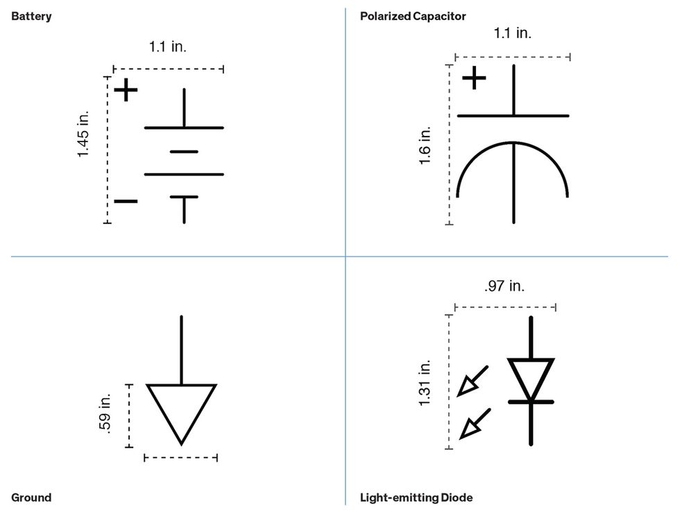 A Symbol Shift: Making circuit symbols larger and tweaking their elements allows them to be printed as tactile diagrams usable by visually impaired makers. Typically, components are labeled with Braille, but testing showed that including positive and negative signs was still helpful (top), as well as using hollow shapes for things like arrows or the Earth symbol (bottom).Diagram: Lauren Race
Race used a methodology called participatory design “where your users are involved in the design process the entire way through.... You partner with blind designers and partner with blind makers. And that was really important to me because as a sighted designer, I have no business making something for somebody whose needs I don't understand," says Race.
Race and her team eventually went through 11 iterations, evolving circuit symbols so they were legible to sighted and blind people alike. They simplified symbols where possible—“we took a lot of noise out"—and made sure there was 6 millimeters of space between subelements so that it was easier to distinguish them: “So the switch opened up. The polarized capacitor was opened up... Even the spacing between the arrows of the LED symbol," says Race. In addition, hollow shapes for elements like arrowheads were chosen over solid shapes “because hollow is tactilely more discernible."
The revised symbols and an accompanying style guide are available for anyone to download and use, along with 50 complete schematics from ITP's physical computing class, at Tactileschematics.com.
This article appears in the July 2019 print issue as “Electronic Schematics for Blind Makers."


