
Once priced out of the reach of enthusiasts, field-programmable gate arrays have become affordable in recent years, and have started popping up in all kinds of neat projects. By the very nature of their reconfigurable hardware, FPGAs can be used in many different ways, such as implementing novel CPUs. But from a maker’s point of view, a huge part of the attraction lies in the circuits’ capacity for handling lots of input/output signals.
Multiple inputs—say, from an array of microphones or other sensors—can be processed in perfect sync, and large numbers of outputs can be generated simultaneously without losing any accuracy in timing. I’ve looked on in envy at FPGA-based undertakings far beyond the capabilities of conventional microcontrollers, such as driving 9,000 smart LEDS. But I’ve been reluctant to dive into FPGAs myself because, in addition to price, there’s been another barrier to entry—learning how to program them. Traditionally, FPGAs are programmed using pro-level hardware-description languages such as Verilog or VHDL. But a new manufacturing partnership between SparkFun Electronics and Alchitry promised a gentle introduction on the programming side and the bonus of easy integration on the hardware side. So I decided to take the plunge and see if that promise could be fulfilled.
As a test project, I settled on building a kinetic sculpture, partially inspired by George Cutts’s motorized sculpture Sea Change, which I’d seen at the outdoor Storm King Art Center during my sole expedition beyond the borders of New York City in 2020. Sea Change uses two rotating elements with their motions locked together. What could I do with many more individually controlled moving pieces?
As the basis for my project, I bought an Alchitry Au Kit for US $130. This comes with the core Alchitry Au board, featuring a Xilinx Artix 7 FPGA with over 33,000 logic cells. The board also comes with eight built-in LEDS, 256 MB of RAM, and a whopping 102 I/O pins that operate at 3.3 volts. It also comes with a Qwiic connector, SparkFun’s open standard for a physical interface for the I²C protocol. Having this connector built right into the board means it’s easy to hook up microcontrollers or sensors from any manufacturer who uses the Qwiic interface.
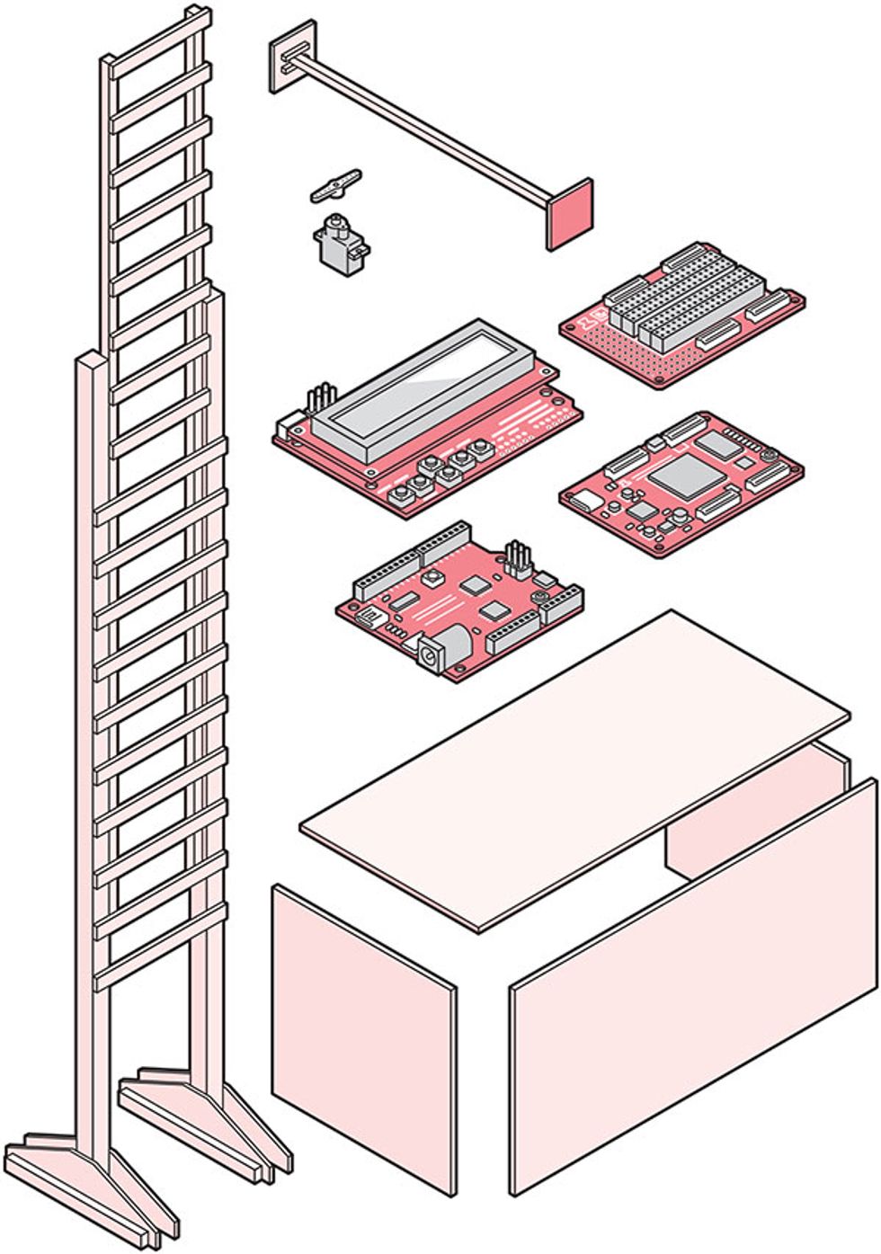 Wood and Boards: The frame and beams of the sculpture are made of light bass wood, while the tiles are made of even lighter balsa wood, to reduce the load on the microservos mounted on each rung. The supporting electronics—an LCD Keypad mounted on a RedBoard microcontroller to provide a user interface—are in the base, and the Alchitry Au FPGA and prototyping board are connected to the individual servos. Wiring runs up behind the sides of the sculpture to the servos.Illustration: James Provost
On the software side, the kit uses Alchitry Labs, an IDE (integrated development environment) designed to run on top of Xilinx’s Vivado package that creates the actual FPGA configuration file. For the record, Vivado runs only on Windows (although I had no problem running it on my Mac under Parallels Desktop), and some folks may not be thrilled that the free version of Vivado has a mandatory reporting function that sends back statistical details about your designs, such as the number of logic cells used.
Alchitry Labs is designed for people programming the Alchitry Au, as well as the cheaper but not quite as sophisticated Alchitry Cu board (which has an FPGA with only 7,680 logic cells and 79 I/O pins but is supported by an open-source tool chain). FPGA programming is done via the Lucid language, which provides some guardrails for novices and useful higher-level abstractions. Projects are prepopulated with the required definitions needed for accessing things like the reset button, onboard LEDs, or the serial interface. A suite of additional components can be added by clicking through a library that contains modules for things like SPI (serial peripheral interface) and I²C, pulse-width modulation, and HDMI encoding and decoding.
An ample set of tutorials is provided, although they could probably do with some tidying up. For example, the documentation I found for using the servo controller was written for the Alchitry’s now discontinued Mojo board, which uses a slightly different way of specifying I/O pins, but it wasn’t too hard to figure out. Many of the tutorials are built around using the I/O Element board that comes with the Au kit, and I was soon driving the Element’s four 7-segment displays to show the output of basic mathematical operations on numbers entered via banks of (teeny tiny) dip switches.
While I’m still very much an FPGA newbie, the tutorials did get me through some of the big mental shifts required for programming hardware versus writing software. You’re not actually writing a program; you’re writing a specification for the tool chain to chew on, and you need to think much more in terms of combinatorial rather than sequential logic.
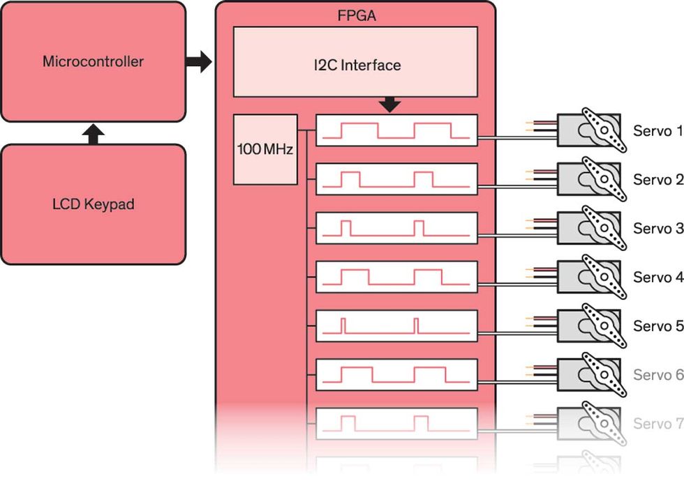 Parallel Pulses: The microcontroller runs a user interface and sends commands to the FPGA via an I²C interface. Inside the FPGA, 18 separate servo controllers running in parallel provide the actual pulse-width-modulated signals used to control each servo’s position every 20 milliseconds.Illustration: James Provost
My sculpture consists of 18 servos arranged vertically, each attached to a horizontal arm with black and red tiles mounted at either end that can oscillate back and forth as desired. Why 18? Well, it’s possible to drive 16 servos with an external servo board connected to a regular microcontroller, and I wanted to push beyond that, but 17 seemed too petty a number. And having many more servos posed its own challenges. When each servo is first energized, it can easily draw 1 ampere before settling down to a few hundred milliamperes in actual operation. Even 18 A is a lot of current to handle at once: My bench supply maxes out at 10 A. I devised a quick-and-dirty power management kludge by dividing the servos into two strings of nine, and added manual switches to the 5-V power lines for each string, letting me energize them one at a time.
Fortunately, the servos will accept a 3.3-V control signal, so I could connect them directly to a protoboard included in the Au kit that plugs onto the FPGA board. The FPGA board controls the servos and in turn takes instructions via a Qwiic connector from a RedBoard Turbo microcontroller, following SparkFun’s outline of using I²C in this way for a clock project. An LCD Keypad shield is mounted on the RedBoard to provide a user interface for controlling servo patterns. The result is a sometimes mesmerizing sculpture, but even more important, I’m now confident enough with FPGAs to consider using them in more projects. Promise fulfilled.


