The Conversation (9)
Greg Mably
DarkBlue1
Auto accidents are responsible for 1.3 million deaths annually, according to the World Health Organization. That’s like losing the city of Prague each year. A switch to self-driving cars and trucks with various types of electronic sensors and sophisticated computers at the helm could save countless lives. But getting this promising technology into people’s hands has been difficult, despite massive research investments and considerable technical progress.
So when will self-driving cars really come to a driveway near you? The answer depends in part on whether such cars require a type of sensor called lidar, short for “light detection and ranging.” Most groups developing autonomous vehicles see lidar as a critical part of the sensor suite required for safe operation, because it allows a detailed 3D map of the vehicle’s environment to be constructed with much more fidelity than can be done with cameras.
Elon Musk, though, has been pushing Tesla to adopt a controversial cameras-only approach to autonomous driving. “Humans drive with eyes & biological neural nets, so makes sense that cameras & silicon neural nets are only way to achieve generalized solution to self-driving,” Musk tweeted in 2021. The mechanical complexity and high cost of most lidar sensors—which not long ago would have added tens of thousands of dollars to the price of each vehicle—no doubt helped shaped Musk’s views. As early as 2016, he declared that “all Tesla vehicles exiting the factory have hardware necessary for Level 5 autonomy”—meaning that cars with cameras and computers alone have what’s needed for fully autonomous driving.
The latest prototype lidar system from Analog Photonics shows off its capabilities at a busy intersection in Boston. Analog Photonics
Seven years and many crashes later, Tesla has not progressed past Level 2 Autonomy, and traffic-safety specialists are questioning Musk’s rejection of lidar. Requiring pricey sensors, though, would slow the widespread rollout of both advanced driver-assistance systems and fully autonomous driving. But reducing the cost of these sensors to a level that would satisfy automakers has remained an elusive goal for lidar manufacturers, which must also consider how to add their devices to cars without detracting from vehicle aesthetics.
We and others at our company, Analog Photonics, which spun out of MIT in 2016, hope to break this impasse. We are developing a tiny, chip-scale phased-array lidar that promises to slash costs and simplify integration. Here we’d like to explain some of the technical challenges we’ve encountered and how very close we are to commercialization.
From Radar to Lidar
Today, more than half of new cars are equipped with one or more radar sensors. These sensors are solid state, cost manufacturers less than US $100 each, and are small enough to be inconspicuously placed around the vehicle. They are used for a variety of things, including automatic emergency braking and adaptive cruise control, as well as lane keeping and other advanced driver-assistance functions.
But this wasn’t always the case. Early automotive radars were large, mechanically steered, emitted short pulses of radio waves, and had limited performance. But the move to electronic scanning and continuous-wave emissions in automotive radars brought performance advancements and cost reductions, which in turn ushered in their widespread use.
Lidar is now undergoing this same evolution. The technology began making headlines around 2016 as a slew of companies, spurred on by the success of lidar sensors on vehicles entered in the DARPA Grand Challenge a decade earlier, began developing custom systems for autonomous vehicles. These systems tended to be pieced together from off-the-shelf components.
 This animation shows how delaying the signal sent from a series of emitters can be used to steer the transmission in different directions. Such phased arrays of emitters are often used for radar, but they can also be used to steer the light beam in a lidar system. Sandeep Sharma
These first-generation lidars went only so far. Spinning or scanning mirrors contributed to their high costs and made their integration into vehicles difficult. They also suffered from reliability issues, and their pulsed operation led to problems in the presence of direct sunlight and resulted in an inherent susceptibility to interference from neighboring lidars. As a result, the available lidar sensors have not met the stringent performance, reliability, and cost goals of the automotive industry.
Carmakers are looking for high-performance, long-range lidar sensors that will cost them less than $500 each. While lidar manufacturers have made progress, the industry isn’t there just yet.
Our company chose to attack these problems head-on by designing lidar sensors that are built entirely on a chip—a photonic integrated circuit made of ordinary silicon. It has no moving parts and generates, emits, and receives light with no external hardware. And its tiny size makes it easy to incorporate into the bodies of even the sleekest cars on the road.
Lidar is a lot like radar, but it operates in the infrared portion of the spectrum, with wavelengths typically between 905 and 1,550 nanometers (compared with a few millimeters for automotive radar). This difference in wavelength gives lidar much better spatial resolution, because the waves sent out from the sensor can be more tightly focused.
Recognizing that the physics of a phased array apply to all frequencies of the electromagnetic spectrum, we decided to use this approach in our solid-state lidar.
Most early automotive lidars, like most early radars, used what is called time-of-flight (ToF) detection. A short pulse of electromagnetic energy is sent out, hits an object, and then reflects back to the sensor, which measures the time it takes for the pulse to complete this round trip. The unit then calculates the range to the object using the known speed of light in air. These systems all suffer from some inherent limitations. In particular, lidars built on this principle are prone to interference from sunlight and from light pulses coming from other lidars.
Most modern radars systems work differently. Instead of sending out pulses, they emit radio waves continuously. The frequency of these emissions is not fixed. Instead, they are swept back and forth across a range of frequencies.
To understand the reason for doing that, it’s important to know what happens when signals of two different frequencies are combined in a way that isn’t purely additive. Doing so will generate two new frequencies: the sum and difference of the two frequencies you initially mixed. This process, called heterodyning, was first demonstrated in 1901 and has since been used widely in radio equipment.
Frequency-modulated continuous-wave (FMCW) radars take advantage of the fact that signals of two different frequencies, when mixed in this fashion, give rise to a signal whose frequency is the difference of the first two. In these radars, the mixing is done between the outgoing signal (or, in truth, an attenuated version of it, often called the local oscillator) and the reflected signal, which differ in frequency because the outgoing signal is, as we mentioned, being swept across a range of frequencies. So by the time the reflected signal makes it back to the sensor, the outgoing signal will have a different frequency from what it had when the now-reflected waves first left the radar antenna.
If the reflected signal took a long time to make the round trip, the difference in frequencies will be large. If the reflected signal took only a short time to bounce back, the difference in frequencies will be small. So the difference in frequencies between outgoing and reflected signals provides a measure of how far away the target is.
 The authors’ lidar consists of two parts: a silicon photonic chip and a semiconductor chip [electron micrograph at left]. The latter contains
the electronics that control the many photonic elements. A higher-magnification
micrograph details the tiny copper bumps that are used to make the electrical
connections between these two chips [right].
ANALOG PHOTONICS
The authors’ lidar consists of two parts: a silicon photonic chip and a semiconductor chip [electron micrograph at left]. The latter contains
the electronics that control the many photonic elements. A higher-magnification
micrograph details the tiny copper bumps that are used to make the electrical
connections between these two chips [right].
ANALOG PHOTONICS
While they are more complex than ToF-based systems, FMCW systems are more sensitive, essentially immune to interference, and can be used to measure the velocity of a target in addition to its distance.
Automotive lidar is now adopting a similar approach. FMCW lidar involves slightly altering the frequency, and thus the wavelength, of the transmitted light and then combining the backscattered light with a local oscillator at the frequency of the transmitted light. By measuring the frequency difference between the received light and the local oscillator, the system can determine the range to target. What’s more, any Doppler shifts from a moving target can also be extracted, revealing the target’s velocity toward or away from the sensor.
This capability is useful for quickly identifying moving targets and discriminating among closely spaced objects that are moving at different speeds. The velocity measurement can also be used to predict other vehicle movements and can even sense a pedestrian’s gestures. This additional dimension to the data, not available from ToF systems, is why FMCW systems are sometimes called 4D lidar.
As you might imagine, FMCW lidar systems use a very different laser source than ToF systems do. FMCW lidars emit light continuously, and that light has comparatively low peak power. The laser power levels are similar to those used in many communications applications, meaning that the light can be generated and processed by photonic integrated circuits. This tiny laser system is one of the key factors that has enabled chip-based lidars.
Steering Light with Phased Arrays
The photonic integrated circuits we designed can be fabricated on standard 300-millimeter-diameter silicon wafers using photolithography, just as is done for most integrated circuits. So we can take advantage of the maturity of the CMOS semiconductor-manufacturing industry to combine all of the various on-chip optical components needed for a full lidar system: lasers, optical amplifiers, waveguides, splitters, modulators, photodetectors, and, in our case, optical phased arrays.
The economies of semiconductor manufacturing slash the cost of each of these components. Having all of them integrated on a single chip helps, too. You see, all lidar systems both transmit light and receive light, and the transmitting and receiving optics must be well aligned. In systems built with discrete optical components, the need for precise alignment adds complexity, manufacturing time, and cost. When things slip out of alignment, the lidar can fail. With integrated photonics, the precise alignment is inherent, because the waveguides carrying the light are lithographically defined.
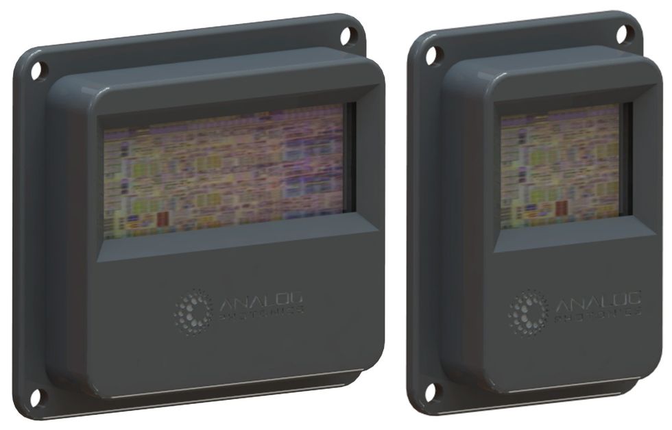 These renderings show what the lidar models now in development are anticipated to look like. The one on the left is designed for long range with a narrow field of view, whereas the one on the right will operate at short range with a wide field of view.ANALOG PHOTONICS
While a handful of companies are working to develop photonic IC–based lidars, only Analog Photonics has figured out how to eliminate the need to mechanically scan the scene with its single-chip lidar. Instead of mechanical scanning, we use what are called optical phased arrays, which allow the beam to be steered electronically.
Scanning is an essential aspect of lidar and one of the key challenges of the technology. The system builds a picture of its surroundings by scanning the scene with one or more laser beams. To detect and identify targets quickly, the lidar must rapidly scan its entire field of view, doing so with sufficiently high resolution to distinguish different objects.
Initially, lidar sensors scanned by either spinning the sensor itself or introducing rotating mirrors into the beam path. The resulting hardware was cumbersome, expensive, and often unreliable.
Although some radars also point their antennas mechanically—as you have no doubt noticed at airports and marinas—some steer the radar beam electronically using phased antenna arrays. This technique adjusts the phase of the signals leaving each of several antennas in such a way that radio waves interfere with one another constructively in one direction and destructively in other directions. By adjusting signal phases at each antenna, the radar can vary the direction in which these signals combine constructively to form a beam.
Electronically phased arrays are the beam-steering technology of choice for automotive radars. Recognizing that the physics of a phased array applies to all frequencies of the electromagnetic spectrum, including optical frequencies, we decided to use this approach in our solid-state lidar. Aided by the Defense Advanced Research Projects Agency through its Modular Optical Aperture Building Blocks program, and with help from several automotive partners (whose names we can’t yet reveal), Analog Photonics has developed on-chip optical phased arrays.
For these arrays, the top surface of the chip is used as both a transmitting and receiving aperture—that’s where the energy leaves and returns to the chip. The on-chip optical phase shifters and emitters are individually controlled with custom electronics to steer exceedingly tight optical beams, ones that are just several millimeters wide.
Achieving a range of steering that’s large enough to be useful requires thousands of closely spaced phase shifters. For example, for a lidar that operates at a wavelength of 1,550 nm, the phase shifters must be placed just 1.5 micrometers apart to enable a 60-degree steering range.
You might wonder how all this optical phase shifting is done. It requires altering the optical properties of the transparent material inside the chip’s many micrometer-scale optical waveguides, which channel the light from the laser where it is generated to the aperture where it is emitted. If you can change the speed of light in that material, you will alter the phase of the light wave exiting the waveguide.
The material here is just silicon, which is transparent to light at infrared wavelengths. One way to alter the speed of light in silicon is to pass sound waves through it, a technique being pursued for use in lidar by researchers at the University of Washington. Another way is to change the temperature: The hotter the silicon, the more the light passing through it is slowed. This is the principle behind what are called thermo-optic phase shifters.
With thousands of phase shifters on a chip, it’s critical that each one consume very little power, mere microwatts. And that’s hard to do when you must heat things up. We sidestepped the need for heating by using electro-optic rather than thermo-optic phase shifters. This approach also enabled us to steer the beam faster, allowing it to step across the field of view at rates exceeding one million scan lines per second.
There remained, though, the challenge of how to connect the many closely spaced optical waveguides with the electronics required to adjust the speed of light within them. We solved this using flip-chip technology: One CMOS chip has thousands of solder-coated copper bumps placed about 75 micrometers apart, or about half the width of a human hair. This scheme allows our silicon photonics chip to be permanently mated with a semiconductor electronic chip containing the needed digital logic and a matching set of copper bumps. Simple commands to the electronic chip then drive thousands of photonic components in the appropriate fashion to sweep the beam.
A Lidar-Rich Future
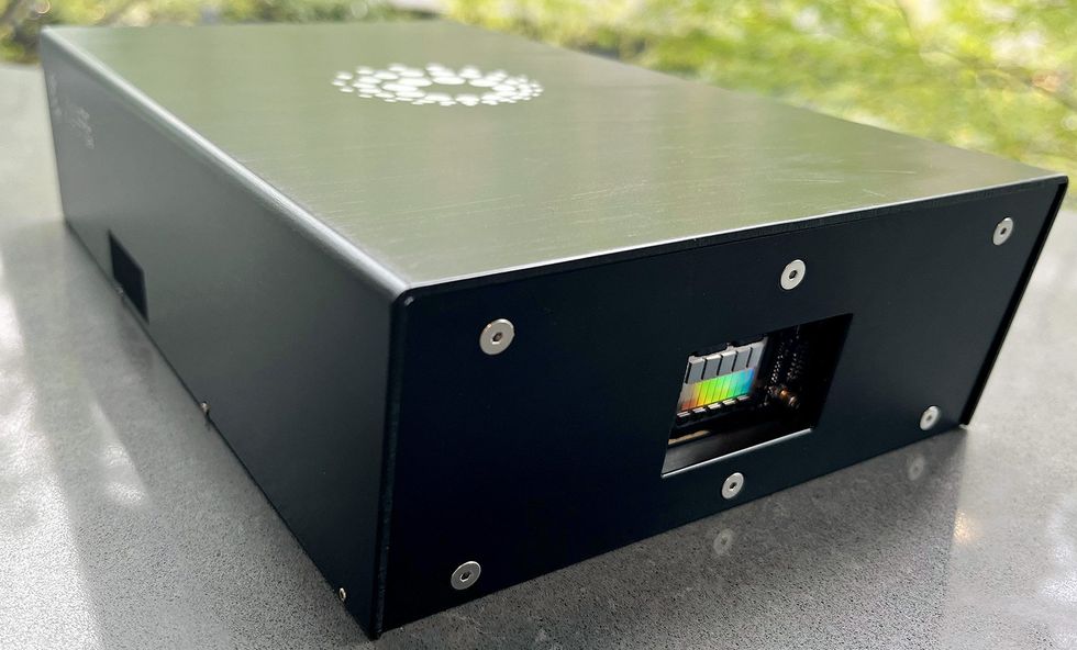 This working prototype for the authors’ long-range lidar is much larger than the finished product will be. Analog Photonics
Analog Photonics has now built and delivered prototypes of the world’s first all-solid-state beam-sweeping lidar to its industry partners, which are companies that supply automotive equipment directly to carmakers. We’ve solved most of the fundamental and engineering challenges and are now focused on increasing the lidar’s performance to meet production specifications. We expect to be turning our creations into actual products and producing large numbers of samples for the automotive industry in 2025.
We are currently working on two different versions of our lidar: a long-range version intended to be mounted at the front of the car for use at highway speeds and a short-range version with a wider field of view to provide complete coverage all around the vehicle. The two sensors have different optical phased arrays in their photonic ICs, while sharing the same back-end signal processing.
We expect that relatively low-cost lidar sensors from some of our competitors, such as Cepton and Luminar, will begin showing up in some top-of-the line cars as early as next year. And driven by the availability of low-cost solid-state sensors like the ones we’re working on, lidar will be common in new cars by the end of the decade.
But the future of lidar won’t end there. Market forecasters expect lidar to be used for many other applications, including industrial automation and robots, mobile-device applications, precision agriculture, surveying, and gaming. And the kind of work we and others are doing with silicon-photonic ICs should help make that bright, lidar-filled future arrive all the sooner.
This article appears in the September 2023 print issue as “Lidar on a Chip Enters the Fast Lane.”
From Your Site Articles
- Lidar-on-a-Chip: Scan Quickly, Scan Cheap ›
- MIT and DARPA Pack Lidar Sensor Onto Single Chip ›
- MIT Spinoff Building New Solid-State Lidar-on-a-Chip System ›
- More LiDAR with Less Data Crunching ›
Related Articles Around the Web
{"imageShortcodeIds":[]}


