
Accurate timing is something that’s always been of interest to me. These days we rely heavily on time delivered to us over the Internet, through radio waves from GPS satellites, or broadcast stations. But I wanted a clock that would keep excellent time without relying on the outside world—certainly something better than the time provided by the quartz crystal oscillator used in your typical digital clock or microcontroller, which can drift by about 1.7 seconds per day, or over 10 minutes in the course of a year.
Of course, I could buy an atomic clock—that is, one with a rubidium oscillator inside, of the sort used onboard GPS satellites. (Not the kind that’s marketed as an “atomic clock” but one that actually relies on picking up radio time signals.) Rubidium clocks provide incredible accuracy, but cost thousands of U.S. dollars. I needed something in between, and salvation was found in the form of the oven-controlled crystal oscillator, invariably known as an OCXO for historical reasons. With one of these, I could build my own clock for around US $200—and one that’s about 200 times as accurate as a typical quartz clock.
Temperature changes are the biggest source of error in conventional crystal oscillators. They cause the quartz to expand or shrink, which alters its resonance frequency. One solution is to track the temperature and compensate for the changes in frequency. But it would be better not to have the frequency change in the first place, and this is where the OCXO comes in.
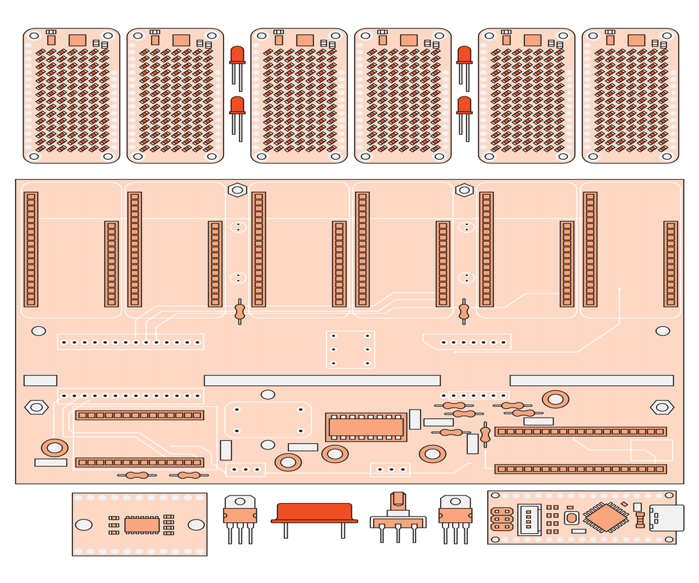 The printed circuit board [center] can be cut into two pieces, with the timing-related components mounted on the lower section, and the control and display components mounted on the upper section.James Provost
The OCXO keeps the crystal at a constant temperature. To avoid the complexity of having to both heat and cool a crystal in response to ambient fluctuations, the crystal is kept heated close to 80 °C or so, well above any environmental temperatures it’s likely to experience. In the past, OCXOs were power hungry and bulky or expensive, but in the last few years miniature versions have appeared that are much cheaper and draw way less power. The Raltron OCXO I chose for my clock costs $58, operates at 3.3 volts, and draws 400 milliamperes in steady-state operation.
The OCXO resonates at 10 megahertz. In my clock, this signal is fed into a 4-bit counter, which outputs a pulse every time it counts from 0000 to 1111 in binary, effectively dividing the 10-MHz signal by 16. This 625-kilohertz (kHz) signal then drives a hardware timer in an Arduino Nano microcontroller, which triggers a program interrupt every tenth of a second to update the clock’s time base. (Full details on how the timing chain and software work are available in an accompanying post on IEEE Spectrum’s website , along with a bill of materials and printed circuit board files.) A rotary controller connected directly to the Nano lets you set the time.
The Nano keeps track of the time, advancing seconds, minutes, and hours, and it also drives the display. This display is created using six Adafruit “CharliePlex FeatherWings,” which are 15 by 7 LED matrices with controllable brightness that come in a variety of colors. Each one is controlled via the addressable I2C serial bus protocol. A problem arises because a CharliePlex is hardwired to have only one of two possible I2C addresses, making it impossible to address six clock digits individually on a single bus. My solution was to use an I2C multiplexer, which takes incoming I2C data and switches it between six separate buses.
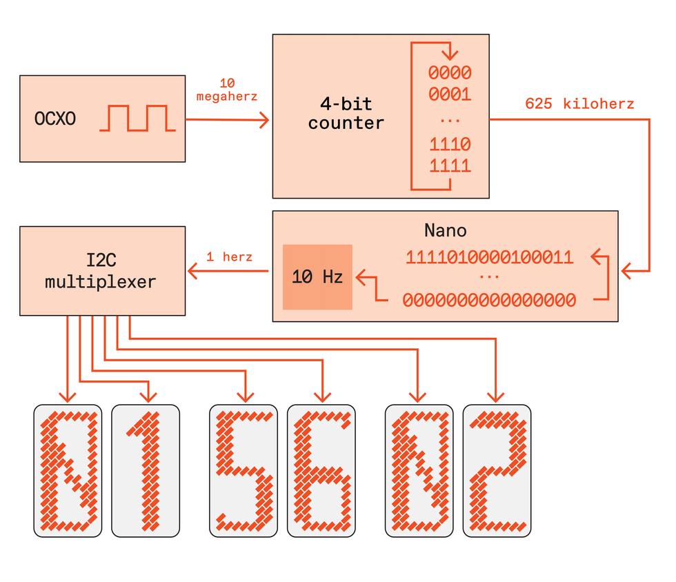 The timing chain begins with the OCXO oscillator and its 10-megahertz signal and ends with the display being updated once every second. The timing signal synchronizes a hardware timer in the Nano microcontroller so that it triggers an interrupt handler in the Nano’s software 10 times a second. Consequently, you can make many modifications or add new features via software changes.James Provost
Using a microcontroller—rather than, say, discrete logic chips—simplified the design and allows for easy modification and expansion. It’s trivial to tweak the software to substitute your own font design for the numbers, for example, or adjust the brightness of the display. Connector blocks for serial interfaces are directly available on the Nano, meaning you could use the clock as an timer or trigger for some other device.
For such a purpose you could omit the display entirely, reducing the clock’s size considerably (although you’ll have to modify the software to override the startup verification of the display). The clock’s printed circuit board is designed so that it can be cut into two pieces, with the lower third holding the microcontroller, OCXO, and other supporting electronics. The upper two thirds hold the display and the rotary encoder. By adding four headers and running two cables between the pieces to connect them, you can arrange the boards to form a wide range of physical configurations, giving you a lot of freedom in designing the form factor of any enclosure you might choose to build for the clock. Indeed, creating the PCB so this was possible was probably the most challenging part of the whole process. But the resulting hardware and software flexibility of the final design was worth it.
The whole device is powered through the Nano’s USB-C port. USB-C was needed in order to provide enough current, as the clock, OCXO, and display all together need more than the 500-mA nominal maximum current of earlier USB ports. A battery backup connected to this port is needed to prevent resets due to power loss—using one of the popular coin-cell-based real-time backup clocks would be pointless due to their relative inaccuracy.
And as for that goal of creating an accurate clock with a great bang for the buck, I cross-checked my OCXO’s output in circuit with an HP 53150A frequency counter. The result is that the clock drifts no more than 0.00864 seconds per day, or less than 3.15 seconds in a year. In fact, its accuracy is probably better than that, but I’d reached the limit of what I could measure with my frequency counter! I hope you’ll build one of your own—it takes just a few hours of soldering, and I think you’ll agree it would be time well spent.


