Beneath the Internet
Explosive Growth Drives Improvements to the Infrastructure
This is part of IEEE Spectrum's special report: Always On: Living in a Networked World.
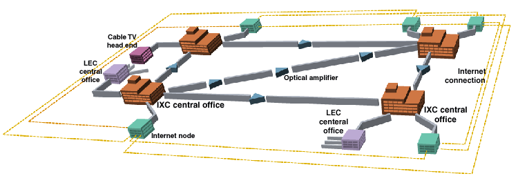
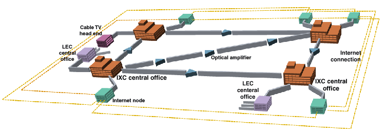
Functionally, the Internet is an interconnection of packet-switched networks based on the TCP/IP protocol suite. On a physical level, it is probably better visualized as a collection of service centers interconnected to a large extent by the same worldwide infrastructure that carries voice and every other kind of communications. [The dashed yellow lines indicate Internet connectivity; the physical connections are via the facilities shown in the diagram, above.]
That infrastructure has two distinct components: the long-haul trunks operated by long-distance service providers (also known as interexchange carriers, or IXCs), and the local loops (also known as subscriber loops and "last mile" connections) that radiate from local service providers to individual customers.
The dominant technology in the long-haul plant is fiber optics, which has a truly enormous (and growing) communications capacity [see "Optical Nets Brace for Even Heavier Traffic,"]. The latest available technology allows a single optical fiber to transport between 1000 and 2000 gigabits of data per second. More advanced technologies will increase those numbers by about an order of magnitude within a year.
The last-mile problem
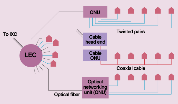
To keep local-loop costs manageable, traditional telephone companies, known as local exchange carriers (LECs), are increasing the capacity of the twisted-pair copper wiring already in place. This they do by installing digital subscriber line (DSL) modems at each end--one in the central office, the other on the customer's premises. The speed they achieve depends on the length and quality of the individual twisted pairs, but it is around a megabit per second. Other ways to access the Internet--cable modems and wireless links--achieve roughly similar results. Cable systems have line speeds of about 50 Mb/s, but that capacity must be shared among multiple users, so user experiences vary greatly.
The buzz is about optics and the long-haul plant, but the last mile is the part to keep your eye on.
Time-Division Multiplexing
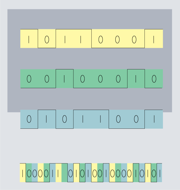
With the advent of digital transmission systems in the 1960s, time-division multiplexing (TDM) became the chief means for combining signals for long-haul transmission. TDM assigns individual data streams (including digitized voice) to time slots in a higher-speed stream [Fig. 2, left]. As the number of multiplexed streams increases, the bit periods get shorter.
Forty and more years ago, long-distance analog phone calls were transmitted over a single coaxial cable or microwave radio link using frequency-division multiplexing. This scheme kept conversations from interfering with one another by assigning each to its own carrier frequency, much as broadcast radio and TV signals still share the air waves.
Central Offices
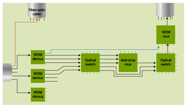
In this hypothetical and extremely oversimplified central office (CO) [Fig. 3, below], one strand of an incoming optical cable [red] is leased by a cable TV company, and is permanently routed to the appropriate outgoing cable, bypassing all of the CO switching equipment. The rest of the strands go to wavelength-division demultiplexers [WDM demuxes], which bring out each wavelength on a separate fiber. One of the wavelengths [blue] from one of those strands is a Sonet OC-48 (2.5-Gb/s) link on long-term lease to an Internet service provider. As such, it is part of the Internet.
The rest of the wavelengths go to optical cross-connects, or switches, which route them as necessary. Some wavelengths are passed along through multiple switches and a wavelength-division multiplexer (WDM mux) onto the appropriate output cable.
Other wavelengths are fed to add/drop multiplexers, which convert the signals from optical to electronic form. Once in that form, a high-speed bit stream can be demultiplexed into multiple lower-speed streams, each of which can be independently routed [not shown].
One such lower-speed stream, an OC-1, for example, which is equivalent to 672 voice channels, may be routed to a local telephone service provider as an electronic signal. Another one might be routed to a local ISP, in which case it is part of the Internet. The point being emphasized here is that Internet and non-Internet traffic often ride not only on the same fiber, but on the same wavelength. They differ only in their assigned time slots.
Other channels may be combined with other traffic bound for the same destination into a new high-speed stream. The add/drop mux will modulate a laser with the new OC-48 signal, converting it back to the optical domain. The fiber carrying the multiplexed information is then routed through another optical cross-connect to a WDM multiplexer (WDM mux), which combines it with many other data streams heading in the same direction and pushes the whole lot of them onto an appropriate strand.
Wavelength-Division Multiplexing
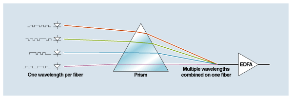
In fiber-optic systems, the 1s and 0s of a high-speed TDM bit-stream modulate a laser by turning it on and off. Several streams [Fig. 4, below], each modulated onto a different laser beam (at a slightly different wavelength), are then combined, as if passed through a prism, for transmission over a single fiber. Each fiber thereby carries many bit streams, in what is known as wavelength-division multiplexing (WDM).
Erbium-Doped Fiber Amplifiers (EDFAs)
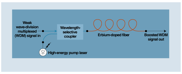
Key to long-haul fiber-optic success is the EDFA, which boosts every wavelength in a fiber strand without causing them to interfere with each other. In an EDFA, a coiled length of erbium-doped fiber is "pumped" by a high-energy laser, [Fig. 5, below] which transfers some of its energy to the erbium atoms, which in turn boost the power of the light waves passing through the fiber.
Local Loops
In the old days, the local loop was simply a pair of wires that ran from a local exchange carrier's (LEC's) central office (CO) to a subscriber's premises. [Fig. 6, below] Increasingly, LECs are breaking these loops into two pieces: a run of optical fiber from the CO to a neighborhood box, and a run of traditional twisted-pair wiring from the neighborhood box to the customer's premises. Each neighborhood box serves multiple subscribers, perhaps several hundred of them.
The optical fiber carries many conversations and/or data streams multiplexed together. The neighborhood box, or optical network unit (ONU), demultiplexes the communications streams coming from the CO and sends them on to the individual subscribers.
Cable uses a similar approach, called hybrid fiber coax (HFC). The difference between telephony and cable plants is that telephone subscribers each get a separate connection to the ONU, whereas cable customers share their last-mile cable run.
