
A couple of months ago, I built the Membership Card, a remake of the 1976 Cosmac Elf microcomputer. Despite the vintage of its RCA CDP1802 processor, the Membership Card still has value as a low-power microcontroller, with an elegant instruction set that leverages a clever hardware design. However, only a masochist would attempt to do any serious programming with the Membership Kit alone: Entering a program via the Membership Card’s front panel requires using toggle switches to enter bytes into memory, one bit at a time.
What’s needed is a way to upload programs written with the aid of those sops to human frailty, keyboards and screens. There are actually a number of ways to get such programs into the Membership Card, which is composed of one circuit board that is a complete microcomputer, with processor and memory, and another board stacked above it, which is the front panel that provides general input/output facilities. One way is to burn a program directly into an EEPROM chip and mount it on the microcomputer board. A more flexible option is to burn a small loader program onto an EEPROM and then upload programs as desired via a serial connection.
To be sure, this is probably the best approach if you intend to use the Membership Card with shields created for the Arduino, for example. Bill Rowe has created a replacement board for the front panel—the Olduino—that allows exactly this, supplying an interface for modern shields that provide things like Ethernet connectivity.
But these options require hardware modifications. Instead, I wanted to use the parallel port interface built into the existing front panel. With this I could build a programmer that would—electronically speaking—act like a human being flipping switches and entering bytes, albeit a fast and error-free one.
Interface In a Box
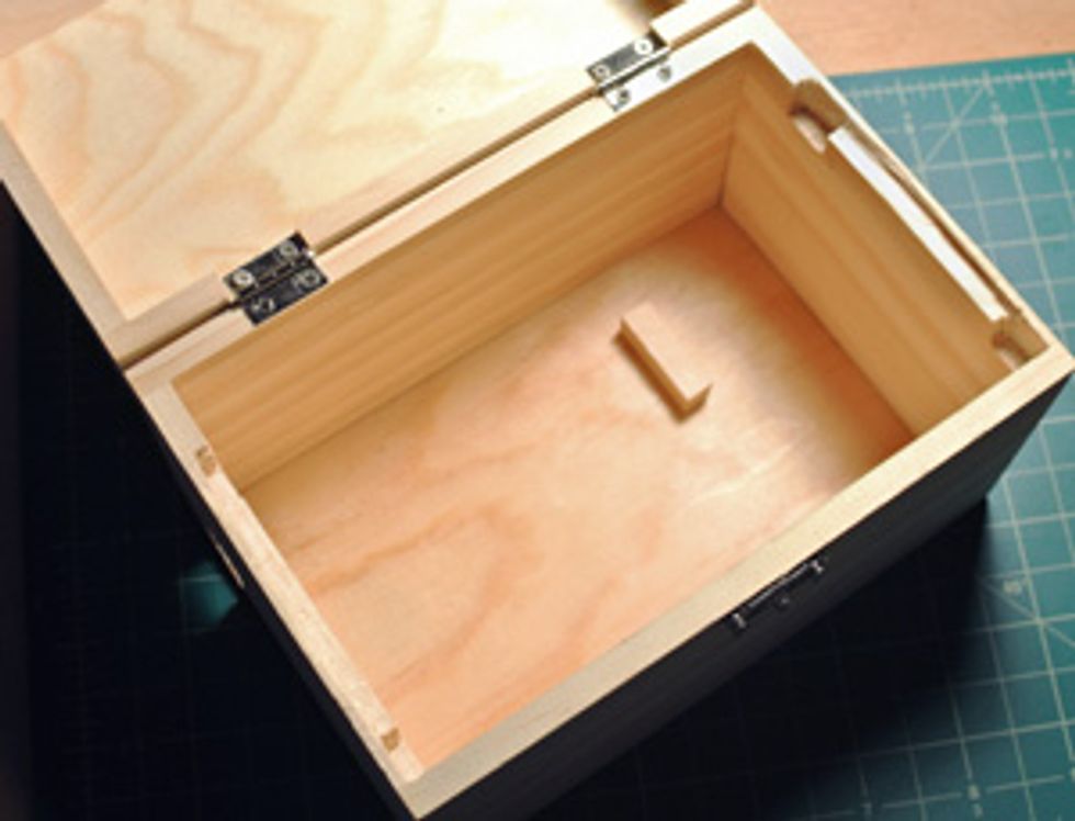
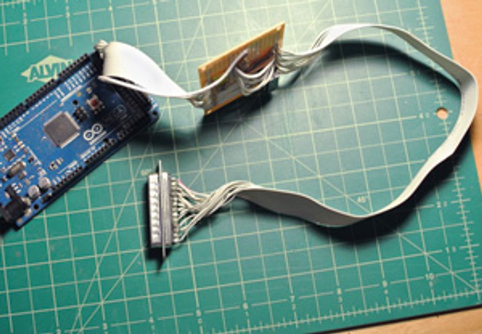
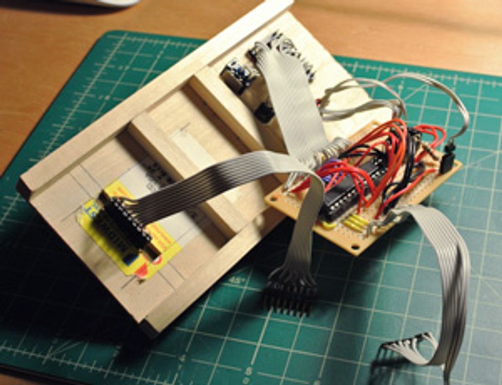
 I cut notches and holes in a box to create an enclosure (top) for the Arduino Mega and two interface boards. The first board connects the Mega to a 25-pin connector (second from top). The second board (second from bottom) controls the LED display (bottom).Photos: Stephen Cass (4)
The original Cosmac Elf used a bunch of chips and hard-wired logic to handle input from a keypad and display output via two hexadecimal digits and a “Q LED.” (The Q LED was connected to a dedicated Q pin on the 1802 that could be turned on or off with a single machine code instruction.) I figured that a standard US $25 Arduino Uno would have enough processing oomph to replace most of those chips with software.
To drive the display, though, I used a MAX6971 [PDF] chip. This let me send serial signals via three of my Arduino’s pins to form numbers and the letters A to F on two seven-segment LEDs. Driving them directly would have required 14 of the Uno’s 20 input/output pins.
But then I realized that even with the MAX6971’s help, my input/output real estate woes weren’t over: I would need eight pins to connect directly with the keypad, another eight pins to send the data bits for each byte of my program, and nine more pins to handle various control signals and the output from the 1802.
I initially thought that a set of shift registers—which convert parallel signals into serial ones and vice versa—would allow me to connect everything up with pins to spare, but with all the additional wiring, I would end up with something that was just as complex as the original Cosmac Elf circuitry.
So I decided to throw some money at the problem and step up to the Arduino Uno’s big sister, the Arduino Mega. The Mega costs about twice as much as the Uno, but it has over three times as many input/output pins. All my real estate woes vanished. I still used the MAX6971 to handle the seven-segment LED displays (to avoid having the Mega handling the relatively large amounts of current that so many LEDs could require), but everything else was wired up directly, including the Q LED. I used resistors on the various input and output lines to act as pull-up resistors and current limiters, respectively. Interfacing with the Membership Card required wiring up 17 pins of a 25-pin parallel connector.
The basic operation of the Membership Card is controlled by three dedicated toggle switches on the front panel that reset the processor, switch it between run and programming modes, and so on. Using guidelines available on the Retrotechnology website, I was able to write software that manipulated various control lines to perform the functions of these switches.
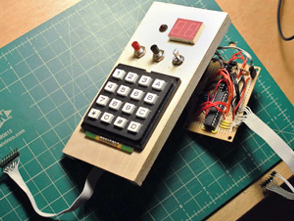
I fitted the programmer into a wooden box that I picked up at an art supply store for a few dollars. My programmer operates in two modes—Load and Run. In Load mode, keying bytes in via the keypad and pressing an input button stores them in the Membership Card’s memory. Pressing another button sends an entire prewritten program to the Membership Card. Currently, this program is coded into my Arduino software, but there’s no reason the software couldn’t be modified to accept programs from a host computer (perhaps one running the excellent TinyElf emulator, so as to fully debug programs before loading them into real hardware). In Run mode, the programmer starts the Membership Card executing whatever program is in memory and accepts output from it. (A confession: I haven’t got the output part working perfectly yet, but I can at least extract and display the Q signal from programs running on the Membership Card.)
A supercapacitor in the Membership Card will preserve the contents of memory for several hours once disconnected from the programmer, giving me ample time to connect the Membership Card to another power supply for stand-alone use.
Once I perfect the programmer’s operation, the next step will be to add a small LCD. This way I can emulate the action of the “Pixie” graphics chip used on later Elf computers, which provided a screen resolution of a whopping 64 by 128 pixels.