
Last year I picked up a Tandy Model 100 at the Vintage Computer Festival East for about US $90. Originally released in 1983, it was the forerunner of today’s notebook computers, featuring a good-quality keyboard and LCD display. It could run for 20 hours on four AA batteries and a month on standby.
Thanks to the work of the Club 100 user group, I was able to tap into a universe of software written for the Model 100 (also known as the M100). Unfortunately, my machine stopped working. I was able to identify the faulty component, and rather than attempt to find a new replacement, I bought a cheap, broken M100 that was being sold for parts on eBay. I extracted the component I needed from its motherboard and repaired my original M100. Then I looked at the now-even-more-broken second M100, still with its lovely keyboard and screen, and thought, “Surely there’s something I can do with this.” How hard could it be to swap out a 40-year-old 8-bit 8085 CPU and motherboard for something more modern?
I’m not the first person to have thought of this, of course. A number of folks have upcycled the M100, but they typically replace the 240-by-64-pixel monochrome display with something with color and much higher resolution, or they keep the original LCD but use it as a text-only display. I wanted to keep the original display, because I like its big, chunky pixels and low power needs, but I also wanted the ability to support graphics and different fonts, as with the original M100. If I could do that, I could use any number of replacement CPUs, thanks to software like CircuitPython’s displayio libraries. But I soon discovered the challenge was in the M100’s deeply weird—by today’s standards—LCD.
The M100’s LCD is really 10 separate displays, each controlled by its own HD44102 driver chip. The driver chips are each responsible for a 50-by-32-pixel region of the screen, except for two chips at the right-hand side that control only 40 by 32 pixels. This provides a total screen resolution of 240 by 64 pixels. Within each region the pixels are divided into four rows, or banks, each eight pixels high. Each vertical column of eight pixels corresponds to one byte in a driver’s local memory.
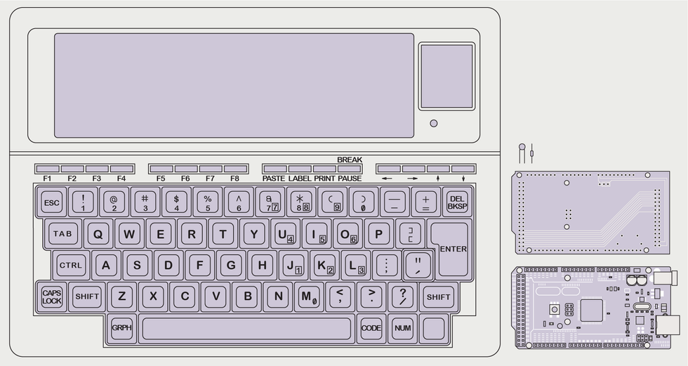 Vintage Tandy M100 computers [left] can be bought for parts for less than US $100. A interface shield along with a resistor and capacitor [right, top] can plug into an Arduino Mega microcontroller and allow you to repurpose the screen and keyboard.James Provost
To set an arbitrary pixel, you determine the screen region it’s in, enable the corresponding driver chip, tell the chip you are sending a command, send the command to select a bank and column, tell the chip you’re now sending pixel data, and then write a data byte that sets eight pixels at once, including the one you want and seven others that come along for the ride.
The reason for this arrangement is that it speeds things up considerably when displaying text. If you have a seven-pixel-high font, plus one pixel of blank space at the bottom, you can copy the font’s bitmap straight from memory byte by byte. Sequential bytes can often be sent without additional commands because the chip automatically advances the column index after receiving a data byte. The order of the banks as displayed can also be altered for fast scrolling.
This bank/column addressing scheme is still used, for example, in some modern OLED displays, but their banks span the entire display—that is, one chip per screen. I would have to manage each region and driver myself.
Cross a wire by accident? No problem, just fix it and try again.
Some things made it easier. First, the M100 was designed to be serviced. The screen drivers sit on a board that interfaces with the motherboard via a 15-by-2-pin connector that can be simply pulled free. The keyboard uses a straightforward 10-by-10 matrix, and also connects via easily detachable connectors. There is a fantastic service manual that gives the details of every single circuit. With the service manual, the HD44102’s datasheet, and some helpful online tips from other folks who’d played with the LCD, I was able to build an interface between the display and an Arduino Mega 2560. And the fact that older machines are often more tolerant of abuse also helped—none of this “give me even a half a volt over 3.3 volts and I’ll let all the magic smoke out” business. Cross a wire by accident? No problem, just fix it and try again. Feed in a raw pulse-width-modulated (PWM) signal instead of a constant analog one? Fine, I’ll just sit here and flicker a bit.
The interface provides the -5 V the LCD needs in addition to +5 V. The interface also hosts a RC low-pass filter to smooth the PWM signal that simulates the 0-to-4 V output of a potentiometer used to adjust the viewing angle. The other pins are passed through to the Mega’s digital input/output or power lines.
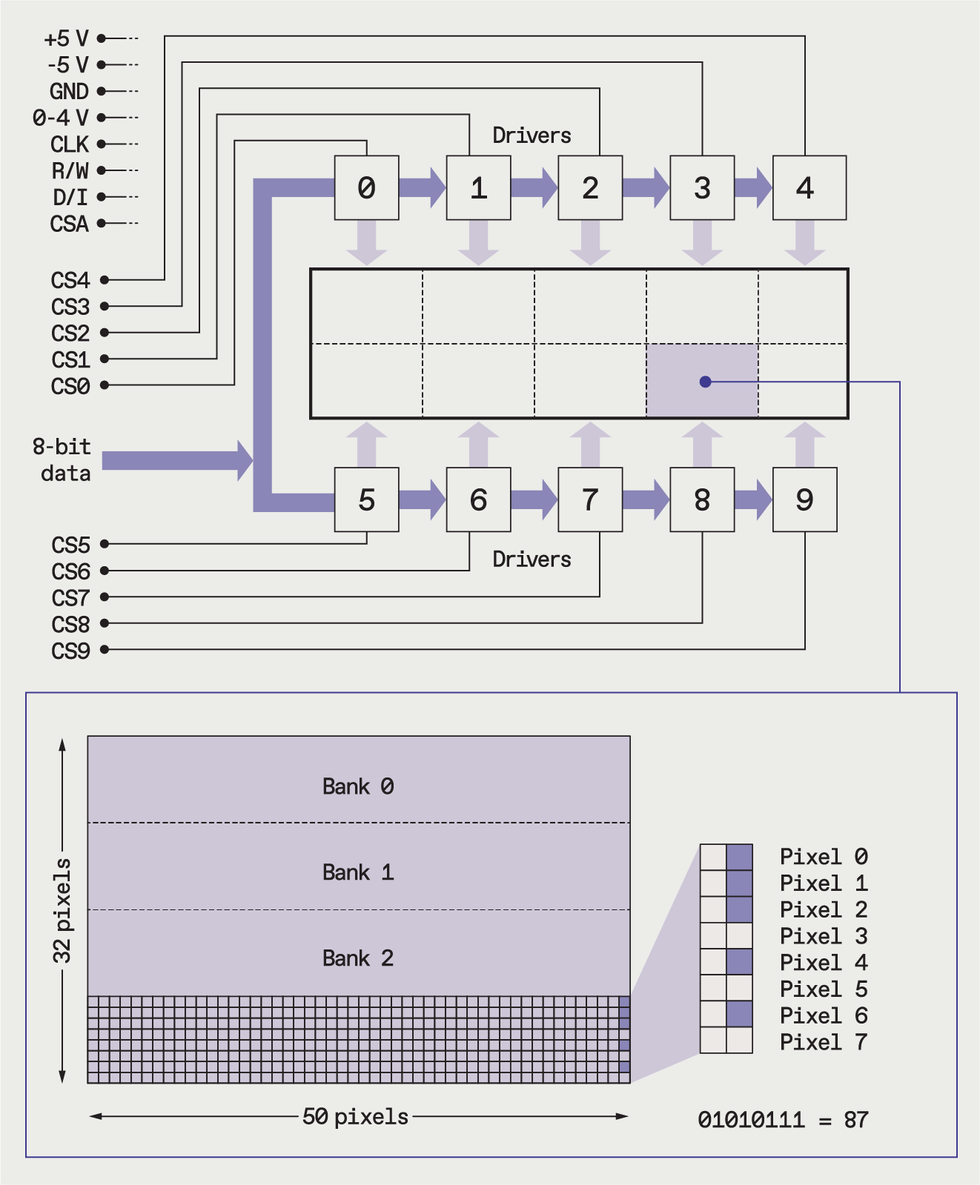 Ten driver chips each control a region of the screen, and must be selected as required by one of 10 chip select lines. Then a bank and column within that row is selected to receive a byte of bitmapped data, setting eight pixels at once.James Provost
I wrote some code to store a 240-by-64-pixel framebuffer and to handle the mapping of its pixels to their corresponding screen regions. The software selects the appropriate chip, bank, and column, sends the data, and manages the various clock and other control signals. The Mega appears to the outside world as the driver of a modern monochrome display, accepting bitmap data as rows (or columns) of pixels that span the screen—exactly the kind of thing that the displayio library can handle.
The LCD can now be hooked up to the microcontroller of my choice via a parallel or serial connection to the Mega, which copies incoming data to the framebuffer; I intend to use a Teensy 4.1, which will allow me to talk to the matrix keyboard directly, have enough compute power for some basic text-editing firmware, and provide a VT100 terminal serial interface—which could be to a Raspberry Pi 4 compute module also mounted inside the M100. That would provide Wi-Fi, a 64-bit OS, and up to 8 gigabytes of RAM—a big step up from the 8 to 24 kilobytes that the case originally housed!
This article appears in the October 2022 print issue as “Upcycling a Tandy Model 100.”


