
 Illustration: Mark Montgomery
The problem has bedeviled designers for decades: How do you squeeze more and more antennas into smaller and smaller mobile devices?
It’s tempting to think that the answer is simply to use smaller antennas or to pack them closer together, but there are fundamental constraints on antenna size and placement. Antennas emit energy in the form of electromagnetic waves, and they do so in many directions. With one antenna, all’s well. But put another antenna next to it and that second one can be swamped by the strong signal coming from the first, making it deaf to the weaker signal it should be receiving.
Two antennas are bad enough. But these days, a typical smart device can have many more. Their ranks usually include one or two antennas for Wi-Fi, one for Bluetooth, one for GPS, and two or four for 4G LTE cellular communications.
This multiplicity of LTE antennas is the norm because it enables the phones to avoid dropouts—including those that occur when your hand obscures one antenna, which can be particularly frustrating during a conversation. Having multiple antennas for the same communications link also allows cellphone carriers to combine multiple streams for improved data transfer rates. And in the near future, 5G communications will add more complexity to the mix, by extending the frequency bands used for cellular below 6 gigahertz, making existing antennas work harder, and by requiring antennas that operate at the 28- and 37-GHz bands.
Device designers have to assume that all the antennas in this gaggle will be operating at the same time. After all, it’s not unusual for a device to be running apps that rely on GPS and Bluetooth while, say, streaming a video over Wi-Fi or the cellular network. Chipset manufacturers have been working to combine functions, such as using one antenna for both Wi-Fi and Bluetooth. Designing two systems to cooperate like this is helpful, but it only chips away at the problem.
So you’ve got a small physical space and lots of antennas that need to operate simultaneously without interfering with one another. Designers have tried to solve this problem by making antennas smaller and more directional. They’ve also endeavored to isolate the antennas more effectively, but that’s tricky given the small amount of real estate there is to work with.
The only sensible solution is a new approach to antenna design. Instead of creating antennas as individual elements and leaving it to the designers to choose where to fit them into a device, it’s better to design a suite of antennas that work well together as a system and then install that system into the mobile device as a single cohesive unit.
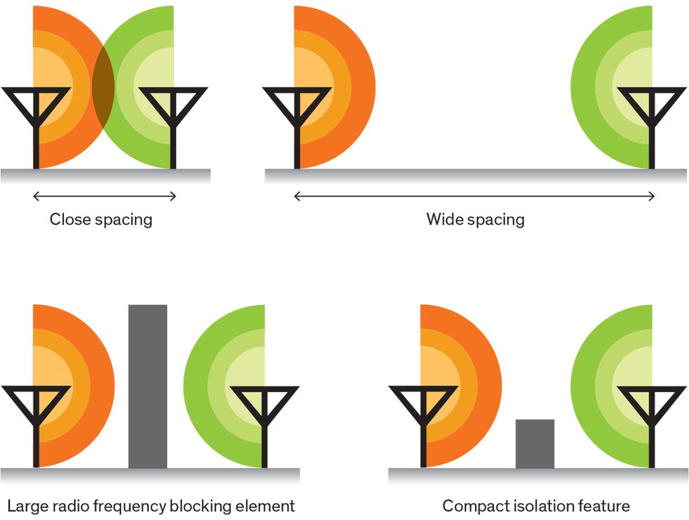 Placement Puzzle: Antennas can create mutual interference. A simple solution could mean either spacing the antennas wide apart or physically blocking the signal path. The first, however, requires more space, and the second would cause the antennas to miss signals from the blocked direction. A better solution is compact isolation, incorporated into the antenna design so that it stops the interference but also lets the desired signals through.Illustration: Mark Montgomery
Before we get into the details of this approach, we should go over some antenna basics. An antenna is simply a transducer, typically made of copper, that (when receiving) picks up energy being sent to it and passes that signal on to a radio chipset. That chipset takes this analog signal and turns it into a digital one, which can then be used by the main processor in the device. When transmitting, this process is reversed.
Antennas, like tuning forks, pick up energy well at only the frequencies at which they naturally resonate. Generally, the resonant frequency of the antenna depends on its physical size, although the frequency can also be modified without changing the size by adding electronic components to “tune” the antenna. To fit antennas into a small space, designers twist them into a wide variety of shapes. There are, however, some physical limitations involving just how close and in what shapes you can make these antennas.
Originally, when mobile phones just had one antenna for cellular reception and transmission, it extended from the handset as a recognizable aerial. Sometimes there was a retractable piece; other times it was just a bump. That was mostly an aesthetic decision, but it did give antenna designers plenty of room in which to optimize the antenna for the best reception.
Today’s sleeker devices have taken away that option, but leaving it there wouldn’t help much: The growing variety of functions found in phones have forced the number of antennas to multiply, so they would never work all crammed into a single antenna bump—mutual interference would destroy their capabilities.
These days, designers are instead distributing the different antennas at various spots around the phone, typically at the edge and rear of the casing. That makes antennas less likely to interfere with one another, but it also makes it difficult to prevent signals being blocked by the user’s hand. Remember the iPhone 4 debacle, when users were furious that merely changing the position of their hands while holding their phones caused the cellular signal to drop? That episode in part triggered the use of multiple antennas at the same frequency, typically paired at the bottom and top of the phone and the top left and bottom right corners.
All Together Now
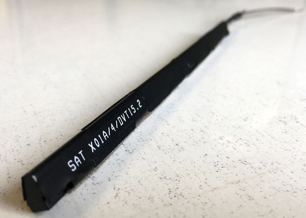
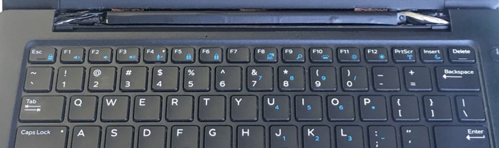 When laptops use traditional antennas, they are distributed along the edge of the device to minimize signal blockage, spaced as widely as possible to reduce interference with one another. Manufacturing all the antennas together as one three-dimensional component (top) allows them to fit compactly along the hinge of the laptop—a good place for clear signal reception—without interfering with one another.Photos: Smart Antenna Technologies
As time has gone on, mobile devices have become slimmer and packed with more functions, thanks in large part to the influence of Moore’s Law on most of the electronics they contain. But Moore’s Law hasn’t helped antennas. Their design is one of the last bastions of analog electronics. With clever engineering—finding new shapes in which to arrange the conductive elements or pairing those elements in various combinations—you can keep the antenna resonating at a desired frequency and make it smaller, but usually you’re not making it better or cheaper. You just reduce its performance, sometimes to the extent that it barely functions as an antenna. One of us personally recalls purchasing one of the early smartphones from Asia and finding that turning on the Wi-Fi prevented the GPS from functioning.
While cramming a bunch of antennas into a tiny phone is hard, the situation isn’t that much better for laptops. It would appear that laptop manufacturers have a lot more room to work with, but they’re increasingly encasing their devices in metal and carbon fiber. Strong and attractive as they may be, these materials are conductive or absorptive, so they block radio signals. As a result, the antennas generally end up in the hinge or in plastic screen bezels, which are increasingly very small strips of real estate.
One company trying to address this problem is Fractus, based in Barcelona. The company has developed a tiny antenna measuring just a few millimeters on a side—Fractus calls it “invisible”—that can perform acceptably in a narrow bandwidth for, say, a single Wi-Fi channel.
Another strategy is to use multiple directional antennas and dynamically select whichever antenna is getting the strongest reception at the desired frequency. This technique can work well and is regularly used in Wi-Fi routers. But it’s less effective in smaller spaces, simply because there are fewer options for antenna shapes and positions, so it’s generally not used in compact mobile devices.
A more traditional way of fitting antennas into a small space without risking interference involves polarization. The concept is similar to what goes on in polarized sunglasses, in which molecules contained in a film coating on the glasses are aligned so that only light waves oriented in a certain way get through, reducing glare. In the simplest scenario, antennas that are placed vertically send out radio waves with a polarization that is at right angles to those placed horizontally, so when antennas in both directions are transmitting, they interfere with one another significantly less than if they were in the same orientation. Similarly, each antenna will have a better chance at receiving a weak, distant signal. Unfortunately, designers find this technique challenging to implement within the physical constraints of today’s products, especially when more than a couple of signals are involved.
At our company,Smart Antenna Technologies, in Birmingham, England, we are taking a somewhat different approach. We accept that the antennas will be crowded together and that they will emit radio-frequency signals that can interfere with one another, so we believe that focusing on the design of one perfect antenna is pointless.
To prevent antennas from being victims of interference, we can and do use standard polarization techniques. But we also make the antennas directional and point them away from one another. We do this by modifying the physical shape of the antenna in three dimensions.
Antenna Jam
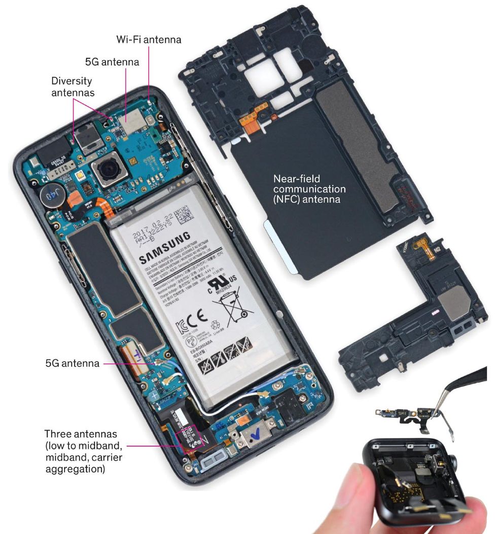 Users of mobile devices demand more and more functionality, requiring designers to pack in more and more antennas. Samsung’s Galaxy S8 includes antennas for Bluetooth, GPS, Wi-Fi, and NFC communications, as well as at least four LTE cellular antennas; used together, they support gigabit-speed data transfers. In the Apple Watch 2 (bottom), the group of antennas (removed) includes Wi-Fi, Bluetooth, and GPS; newer models include LTE cellular.Photo: iFixit
We also try to make it easier for antennas to ignore extraneous signals, using filters in a nontraditional way. Normally, the filters used in antennas are bandpass filters. That is, they allow only signals in the desired frequency band through. Today, this kind of filtering is typically done digitally. The problem with digital bandpass filters is that they don’t get applied until after the analog signal reaches the receiver and is converted to a digital stream. That’s too late to avoid what radio engineers call the “desense” problem: If the out-of-band signals that need to be blocked have enough energy, the receiver can’t detect quieter signals while those high-powered signals are present and for a short period afterward; the difference in energy can be vast—say, 1 watt for the unwanted signals compared with 3 milliwatts for the target signals.
Our approach is essentially the opposite. We know the frequencies at which the surrounding antennas are transmitting, so our analog filters look for those specific frequencies and, in effect, short those signals to ground, dissipating their energy while passing the desired signals undisturbed to the receiver. We also use standard analog design techniques. For example, we use signal matching to identify transmissions at the desired frequency. But the key to our approach is doing the filtering at the front end, in the analog realm, and dynamically changing the signal before it passes to a standard receiver and an analog-to-digital converter.
With all this technology in use, we can place antennas physically close together, within just a few centimeters. But positioning them properly in three dimensions so they all work in harmony isn’t easy. We can’t leave that step up to the device designers or manufacturers, so we aren’t producing individual components. Instead, we’re manufacturing the entire set of antennas needed for a mobile device on one flexible 0.44-millimeter-thick printed circuit board. Flexibility reduces the cost of manufacturing because it lets us start the process in two dimensions and then turn it into a 3D package—by molding a plastic shape and then wrapping it with the flexible circuit board.
One of those shapes appears long and thin. In cross section, though, it is triangular. Our circuit board, wrapped around that, folds at the points of the triangle. Some of our antennas form L shapes in this way, others are rectangular, and still others are custom designed to fit the space inside a particular device.
For very-high-performance antennas, we have started using a more precise manufacturing method—Laser Direct Structuring—that allows us to create far more complex plastic shapes and build our antenna structure directly on top of them. That technique starts with an injection-molded part made out of plastic doped with a nonconductive metal. A laser then draws the pattern of circuits on the plastic. The metal additive causes the areas hit by the laser to roughen. When the material goes through an electrodeless plating process, these rough areas fill with copper or other conductive metals.
We think this kind of approach to antenna design is the way of the future because the demands on mobile device antennas are only going to get tougher.
Data transfer speed will be pushed higher. Today’s 4G is typically capable of delivering up to 100 megabits per second, but 5G is expected to deliver between 1 and 10 gigabits per second. That will require increasing bandwidth; there’s some talk of going to bandwidths as large as 2 GHz. And frequencies are going up, with 28-GHz and 70-GHz frequencies slated for 5G.
Because of the high frequencies at which 5G will operate, mobile devices will be using arrays of similar antennas to get reasonable performance, aligning the signals by phase shifting and then combining them into one signal of the required strength. Given that phones will also have to carry the full set of legacy antennas, at least for the immediate future, the increased competition for space inside mobile devices will make an integrated antenna a necessity.
The first commercial antennas from our company using these techniques started to show up in tablets and laptops from major manufacturers in July. And by the end of this year, we expect to see this technology appear in its first mass-market Internet-of-Things product. That may well represent the largest application of this technology in the future.
Sure, jamming antennas into phones is hard. But the challenge of fitting multiple antennas into the tiny space available in a typical IoT device is even more daunting. Nevertheless, commercial examples demonstrating that this challenge can indeed be overcome are just around the corner. When you see them, you’ll now have a pretty good idea how they can work as well as they do.
This article appears in the November 2018 print issue as “Solving the Antenna Paradox.”
About the Authors
Sampson Hu is the founder and CEO of Smart Antenna Technologies, in Birmingham, England. David Tanner is the company’s business development director.