Millimeter-wave communication is coming. Along with it comes mm-wave antennas and greater challenges in testing. Gone are the days when antenna calibration for far-field characterization revolved around football-field-size installations and towers tens of meters tall. By the 1960s, antenna testing for near-field measurements moved indoors; those results could then be extrapolated to real-world far-field values.
Properly testing today’s antennas requires measurements at thousands of positions, each accurate to within one-hundredth of a wavelength. For signals at 183 gigahertz (the emission line for atmospheric water vapor absorption), which have a wavelength of 1,638 micrometers, the probe must be within 33 μm of its ideal position in every dimension on every measurement. (To properly calibrate an antenna at 500 GHz will require positioning accurate to within 15 μm.)
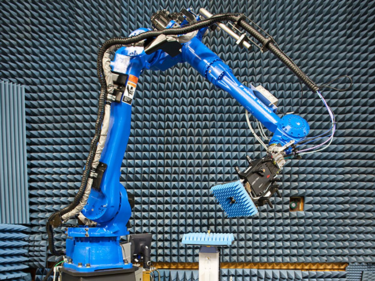
With that in mind, researchers at the Communications Technology Laboratory of the National Institute of Standards and Technology (NIST) in Boulder, Colo., have coupled off-the-shelf components with innovative feedback controls to build a Configurable Robotic Millimeter-Wave Antenna (CROMMA) test facility—a breakthrough for millimeter-wave research and, possibly, the prototype for an “all-in-one” antenna tester. NIST researcher Joshua A. Gordon and his colleagues describe CROMMA in IEEE Transactions on Antennas and Propagation.
In place of the traditional array of rotary tables and individual actuators used to jockey probe and test antennas into positions, CROMMA uses industrial robots: a six-axis Yasawa Motoman MH50-35 robot arm and a six-axis controller to position the test probe, and a hexapod robot (Physik Instrumente M-840) and rotating stage to position the antenna under test. Together, these components control position along three axes, plus angular pitch, yaw, and roll.
The robot arm can position a 35-kilogram probe almost anywhere in a 1-meter-radius working volume. The test-antenna support can maneuver a 30-kg load within a 25-by-25-by-50-mm box, and can vary the tilt within a range of 15 to 30 degrees.
The hexapod accuracy is well within the single micrometer that mm-wave requires. The probe arm, however, comes out of the box with a 70-μm limit on position repeatability.
To gain greater precision, the developers added several layers of feedback control. They started with a laser tracking system comprising an array of spherical mirror reflectors mounted on the test floor, the robot arm, and the test antenna table. They further increased precision by mounting “more sophisticated” commercial laser targets the probe arm. Finally, they added a set of three machine vision cameras to double-check the probe’s position from outside the moving robot-hexapod system.
To integrate these overlapping sets of position and rotation information and attain final accuracies within 25 μm in position and 0.01 degrees of rotation, the NIST team developed a Coordinated Metrology Space (CMS). The CMS combines the separate reference frames of the probe, the test antenna, the hexapod, and the rotating stage under the hexapod. The result is an extraordinarily precise picture of the relative positions and orientations of the probe and test antenna.
The group used a commercial 50-GHz vector network analyzer (with a frequency extender) to generate the signal from the test antenna and measure the signal amplitude and phase at the probe antenna. The tight control allowed the engineers to move the probe accurately through almost any path—including the spherical, cylindrical, and planar configurations commonly used to calibrate antennas. The 100-mm-radius spherical near-field test, for example, required 76,000 separate probe locations. The root mean square (rms) radius actually measured was 99.977 mm, with an rms error of 22 μm.
The NIST researchers checked the system by extrapolating far-field signal values from the 100-mm near-field data, and then comparing the extrapolations with data actually collected from far-field runs at radii of 1000 mm from the test antenna. The agreement was very close (with some increase in noise at wide angles between transmitter and probe).
In sum, the authors say, CROMMA makes it possible to have a single facility capable doing tests that previously required multiple antenna set-ups, “thus making possible a truly all-in-one antenna characterization facility.” More work is required to reach that goal, of course—particularly an increase in positioning accuracy to meet the demands of 500 GHz components.
Douglas McCormick is a freelance science writer and recovering entrepreneur. He has been chief editor of Nature Biotechnology, Pharmaceutical Technology, and Biotechniques.


