
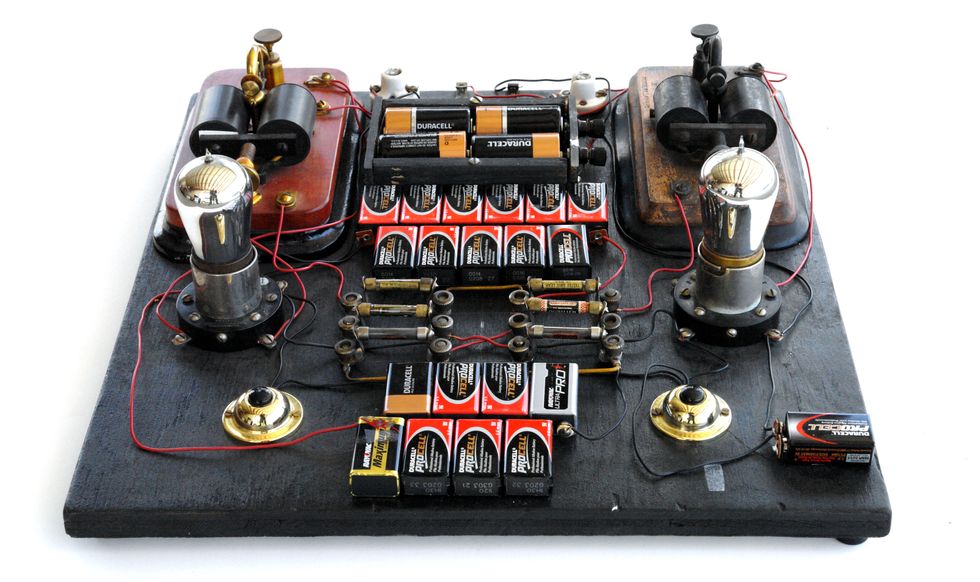
 Photo: Richard Brewster
Many engineers are familiar with the names of Lee de Forest, who invented the amplifying vacuum tube, or John Bardeen, Walter Brattain, and William Shockley, who invented the transistor. Yet few know the names of William Eccles and F.W. Jordan, who applied for a patent for the flip-flop 100 years ago, in June 1918. The flip-flop is a crucial building block of digital circuits: It acts as an electronic toggle switch that can be set to stay on or off even after an initial electrical control signal has ceased. This allows circuits to remember and synchronize their states, and thus allows them to perform sequential logic.
The flip-flop was created in the predigital age as a trigger relay for radio designs. Its existence was popularized by an article in the December 1919 issue of The Radio Review [PDF], and two decades later, the flip-flop would find its way into the Colossus computer [PDF], used in England to break German wartime ciphers, and into the ENIAC in the United States.
Modern flip-flops are built in countless numbers out of transistors in integrated circuits, but, as the centenary of the flip-flop approached, I decided to replicate Eccles and Jordan’s original circuit as closely as possible.
This circuit is built around two vacuum tubes, so I started there. Originally, Eccles and Jordan most likely used Audion tubes or British-made knock-offs. The Audion was invented by de Forest, and it was the first vacuum tube to demonstrate amplification, allowing a weak signal applied to a grid to control a much larger electrical current flowing from a filament to a plate. But these early tubes were handmade and unreliable, and it would be impractical to obtain a usable pair today.
Instead I turned to the UX201A, an improved variant of the UV201 tube that General Electric started producing in 1920. While still close in time to the original patent, the UV201 marked the beginning of vacuum-tube mass production, and a consequent leap in reliability and availability. I was able to purchase two 01A tubes for about US $35 apiece.
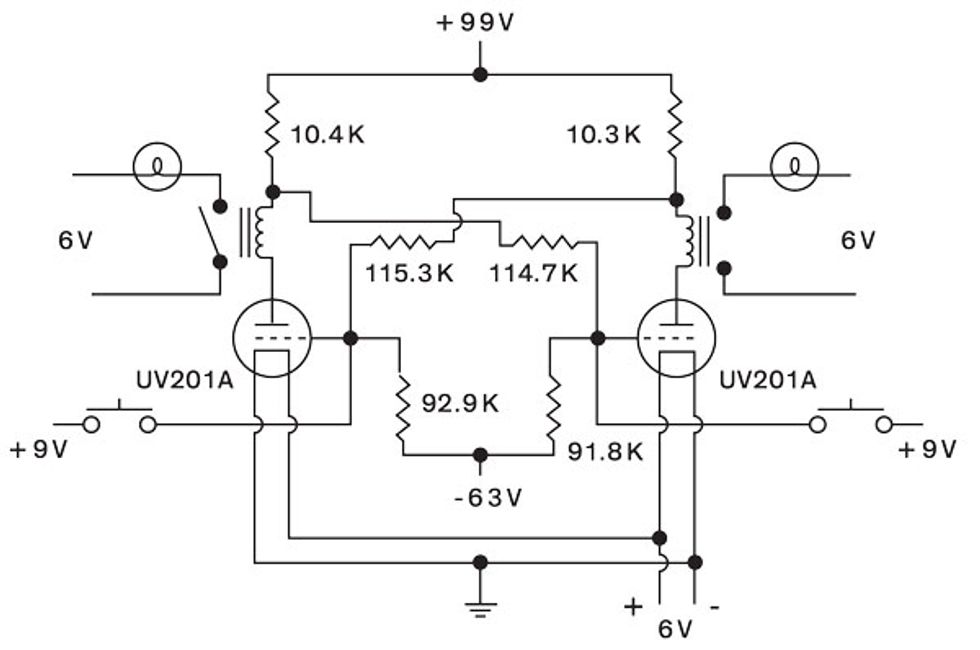
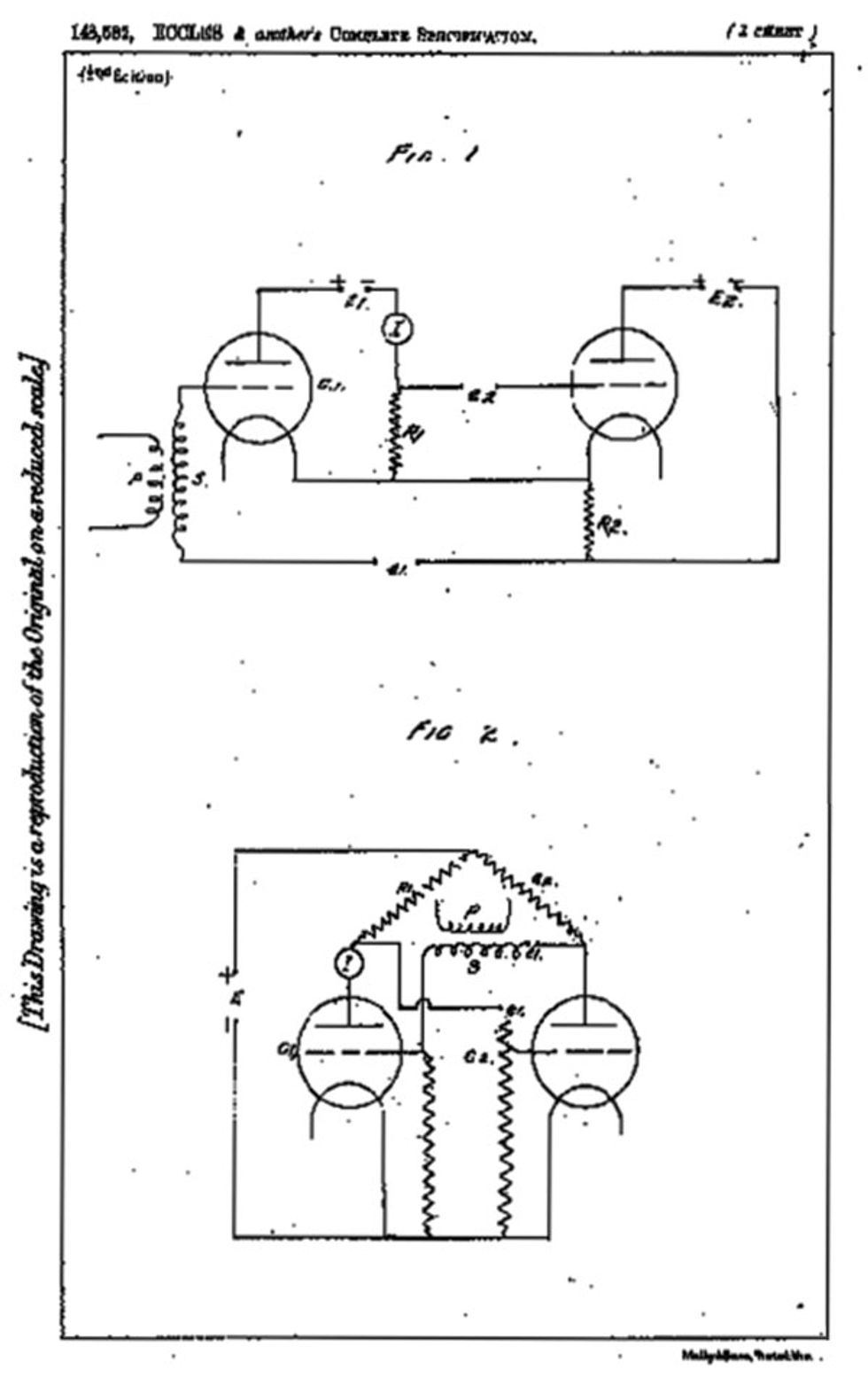 Circuit Revival: Working from drawings in sources such as Eccles and Jordan’s patent (bottom), I re-created the circuit and then adjusted resistances through trial and error (top).Top: Richard Brewster and Erik Vrielink; Bottom: Intellectual Property Office
In a flip-flop, the tubes are cross-coupled in a careful balancing act, using pairs of resistors to control voltages. This balancing act means that turning off one tube, even momentarily, turns the second tube on and keeps the first tube off. This state of affairs continues until the second tube is turned off with a control signal, which pushes the first tube on and keeps the second tube off.
Achieving the right balance means getting the values of the resistors just right. In their laboratory, Eccles and Jordan would have used resistor decade boxes, bulky pieces of equipment that would have let them dial in resistances at different points in their circuit. For reasons of space, I decided to use fixed resistors of a similar vintage as the patent.
I was able to obtain a set of such resistors from the collection of antique radios that I’ve accumulated over the years. In the 1920s, radio manufacturing exploded, and the result is that I have quite a few early radios that are pretty nondescript and beyond repair, so I didn’t feel too bad about cannibalizing them for parts. Resistors made before 1925 were generally placed into sockets, rather than soldered into a circuit board, so extracting them wasn’t hard.
The hard part was that these resistors are very imprecise. They were handmade with a resistive carbon element held between clips in a glass enclosure. One way to get their resistance closer to the desired value is to open up the enclosure, remove the strip of carbon, make notches in it to increase its resistance, and put it back in. I adjusted several of the resistors this way, but it was too tricky to do with others, so for those I cheated a little and placed modern resistors inside the vintage glass casing.
I used modern battery supplies, in order to avoid the use of the numerous wet cells that the inventors probably used. One of the issues with tube-based circuits is that a range of voltages is required. Four D cells wired in series provides the 6 volts needed for the indicator lamps and the filament of the tubes. Connecting eleven 9-V batteries in series provided the 99 V required for the tubes’ plate. A similarly constructed 63-V power supply is needed to negatively bias the tubes’ grids. Old-fashioned brass doorbell buttons let me tap a 9-V battery connection to provide the control pulses. To show the flip-flop’s state, I used sensitive antique telegraph relays that operate miniature incandescent lamps.
With a lot of trial and error and tweaking of my nearly century-old components, over the course of a year I was finally able to achieve stable operation of this venerable circuit!
If you are looking to replicate my efforts, and are willing to sacrifice some more historical accuracy for much greater ease in obtaining reliable parts, there are some good options. Some 6J5 tubes, first manufactured in the late 1930s, are a fine choice. These are reliable and a lot cheaper than the 01As, costing about $5 to $7 apiece.
The telegraph relays and the lamps can be eliminated and replaced with inexpensive NE-2 neon lamps. The latter would be wired between the plate of the 6J5 and the batteries, so as to illuminate when the tube is not conducting and extinguish when the tube conducts, thus dropping the plate voltage to a low value. Note that the 6J5 is a cathode-type tube, and so the cathode should be grounded and the filaments separately supplied by a 6-V battery, unlike in the original circuit.
The grid bias battery voltage selection will require some experimentation, as the 6J5 will likely require a lower value than the 63 V used with the 01As. And with regard to the resistances used, the values shown can be assumed to be approximate, but some effort should be made to have the three pairs rather closely matched.