Before flat screens, before even cathode-ray tubes, people watched television programs at home thanks to the Nipkow disk. Ninety years ago in places like England and Germany, broadcasters transmitted to commercially produced black-and-white electromechanical television sets, such as the Baird Televisor, that used these disks to produce moving images. This early programming established many of the formats we take for granted today, such as variety shows and outside broadcasts.
The size and weight of a Nipkow disk makes a display with more than a few dozen scan lines impracticable (in stark contrast to modern screens with thousands of lines). But when a mechanical TV is fed a moving image, the result is surprisingly watchable. And Nipkow displays are fascinating in their simplicity—no high voltages or complex matrices. So I wondered: What was the easiest way to build such a display that would produce a good quality image?
I’d been interested in Nipkow disks since I was a student, trying a few experiments with cardboard disks that didn’t really produce anything. In more recent years, I saw that a number of people had built modern Nipkow displays—even incorporating color—but these relied on having access to pricey machine tools and materials. I set about designing an inexpensive version that could be made using a consumer-grade 3D printer.
The secret of a Nipkow disk is in its spiral of holes. A light source behind the disk illuminates a small region. A motor spins the disk, and each hole passes through the lighted region in turn, creating a series of (slightly curved) scan lines. If the illumination is varied in sync with the time it takes each hole to cross the viewing region, you can build up images in the display frame.
The first thing I had to do was figure out the disk. I chose to make the disk 20 centimeters in diameter, as that’s a size most home 3D printers can manage. This dictated the resolution of my display, since there’s a limit to how small you can produce precisely shaped and positioned holes. I wrote software that allowed me to generate test disks with my Prusa i3 MK3S+ printer, settling on 32 holes for 32 scan lines. The display is a trapezoid, 21.5 millimeters wide and 13.5 mm tall at one end and 18 mm tall at the other. One unexpected benefit of printing a disk with holes, rather than drilling them, was that I could make the holes square, resulting in a much sharper image than with circular holes.
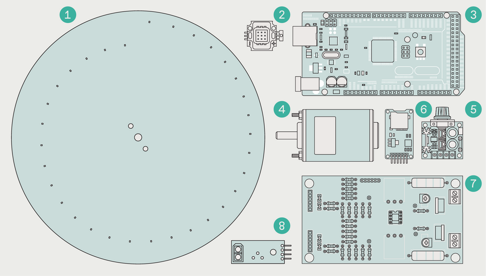 A printed 20-centimeter-diameter disk (1), complete with 32 holes, is illuminated by an RGB LED module (2). An Arduino Mega (3) controls the LEDs, while the motor’s (4) speed is adjusted by a potentiometer (5). Images and movies are stored and read from a SD card (6). Digital LED data from the Mega is converted to analog voltage using a custom PCB (7), and the rotation of the disk is monitored with an infrared sensor (8).James Provost
For a light source, I used an LED module with red, green, and blue elements placed behind a diffuser. A good picture requires a wide, dynamic range of brightness and color, which means driving each element with more power and precision than a microcontroller can typically provide directly. I designed a 6-bit digital-to-analog converter circuit, and had custom printed circuit boards made, each with two copies of the circuit. I stacked two PCBs on top of each other so that one copy of my DAC drives one LED color (with a spare circuit left over in case I made any mistakes populating the PCBs with components!). This gives a combined resolution of 18 bits per pixel. Three potentiometers let me adjust the brightness of each channel.
An Arduino Mega microcontroller provides the brains. The Mega has enough RAM to hold screen frames and enough input/output pins to dedicate an entire port to each color (a port allows you to address up to eight pins simultaneously, using the bits of a single byte to turn each pin on or off). While this did mean effectively wasting two pins per channel, the Mega has pins to spare, and addressing a port provides a considerable speed advantage over bit-banging to address each pin separately.
One unexpected benefit of printing a disk was that I could make the holes square, resulting in a much sharper image.
The Mega synchronizes its output with the disk’s rotation using an infrared sensor triggered by a reflective strip attached to the back of the disk. Thanks to this sensor, I didn’t have to worry about precisely controlling the speed of the disk. I used a low-noise 12-volt DC XD-3420 motor, which is easily obtained.
I connected some additional controls to the Mega—a mode button that switches between photos and videos, a play/pause button, and a skip-track button to advance to the next file. Frames printed in 3D hold everything together, mounted on a wooden base.
Because my TV uses 6 bits per channel per pixel instead of the 8 bits used by most modern image formats, I created a conversion tool that is free to download, along with all of the other supporting files for this project from Hackster.io. Videos are treated as a collection of still images sent to the display at a rate of about 25 to 30 frames per second, depending on the exact speed of the disk. You can convert video into suitable collections using the open-source software VirtualDub, and then pass the results through my converter.
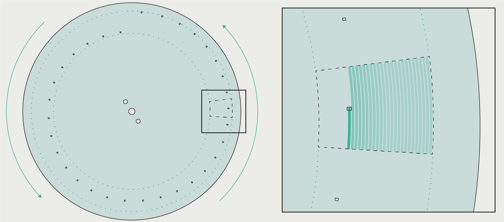 As each hole moves in front of the LED light source, the brightness of the LED is modulated to create a scan line of the image.James Provost
Movies and images are stored on a SD card and read into the Mega’s memory using an SD module via its SPI connection. The TV simply scans the top-level directory and begins displaying images—one at a time in the case of photos, and automatically advancing to the next image in video mode. Initially, when I tried to play movies there was noticeable stuttering thanks to dropped frames. I discovered this was due to the standard Arduino SD library—it can handle data transfers at a rate of only 25 kilobytes per second or so, while at 25 frames per second the display is looking for data at a rate of 75 kB/s. The problem was solved by switching to the optimized SdFat library, which provides much faster read access.
The result is a display that’s small enough to fit nicely on a desk or shelf, but produces a bright, colorful, and steady image at a frame rate fast enough for most video. All-electronic television may have ultimately triumphed over mechanical sets, but my spinning Nipkow disk is a visceral reminder that powerful forces can spring from simple origins.
This article appears in the June 2022 print issue as “EZ Mechanical TV.”
- 3D-Printed OLEDs Enable DIY Screens Nearly Anywhere - IEEE ... ›
- Consumer Electronics Timeline - IEEE Spectrum ›
- How RCA Lost the LCD - IEEE Spectrum ›