
In the 1968 movie 2001: A Space Odyssey, an oddness in the moon’s magnetic field leads scientists to an alien monolith buried under Tycho crater. The notion of being led to a hidden object by virtue of the magnetic anomaly it creates must have really intrigued my 9-year-old self, because a decade after seeing that movie I decided to build a circuit to measure the strength of Earth’s magnetic field. So I read some World War II–era journal articles and learned about the magnetometers used to locate submerged German submarines. With that information, I constructed what’s called a fluxgate magnetometer. It was crude, but it worked.
I was reminded of that project by a recent IEEE Spectrum feature about magnetic amplifiers, which rely on metal alloys that become highly magnetized in the presence of a magnetic field. These alloys tend to saturate, meaning that they cannot become further magnetized as the field increases. Magnetic amplifiers and fluxgate magnetometers both make use of this phenomenon.
That jog down memory lane led me to read about a different type of magnetic-field sensor that also relies on such alloys: something called a magneto-inductive magnetometer, which appears to have first been commercialized around 2010. This magnetic-field sensor is surprisingly simple, so I headed to the garage to see whether I could build this type of magnetometer just with stuff I had on hand.
Amazingly, I managed to locate a tattered envelope containing pieces of the magnetic alloy (Mu-metal) that I had used decades ago to build a fluxgate magnetometer. And that was the only hard-to-obtain item I needed.
I scrounged a 6-millimeter-diameter plastic tube, which I put into the chuck of an electric drill and wound a few hundred turns of 32-gauge magnet wire around it. I then stuffed five slender pieces of Mu-metal into the tube.
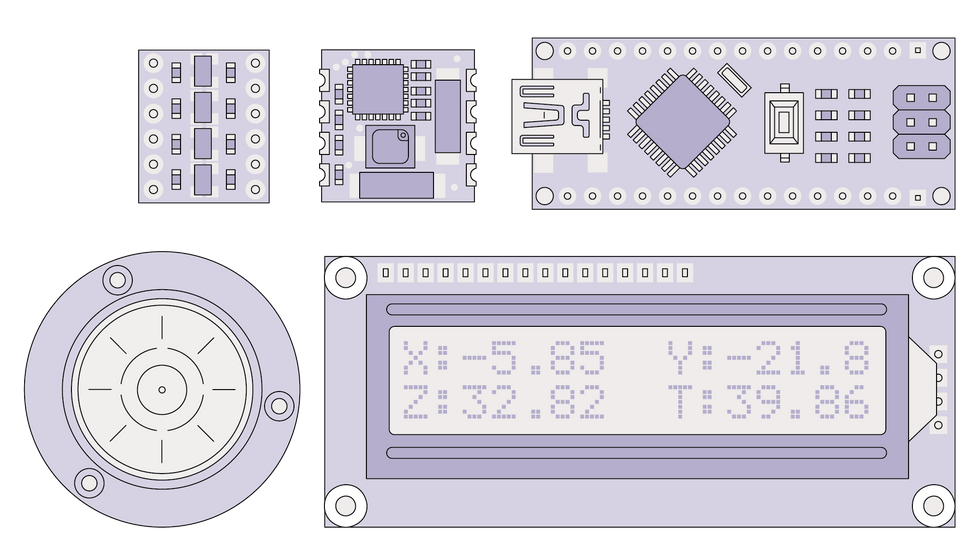 The project involves [clockwise from top left] four small and inexpensive circuit boards—a level shifter, an RM3100 sensor, an Arduino Nano, and an LCD display—along with a bull’s-eye level.James Provost
In addition to this coil, my homebrew magneto-inductive sensor required just three resistors and one LM358 chip, which contains two op amps. One op amp is wired to two resistors to form an inverting Schmitt trigger: a comparator with two different voltage thresholds. When the input voltage rises past one threshold, the output switches negative; when the input falls below the second, lower threshold, the output switches positive. The third resistor is attached to the trigger’s input, with the coil providing feedback.
This arrangement [schematic diagram below] creates a relaxation oscillator, the output of which looks quite funky on an oscilloscope. But feeding it to a second op amp configured as a simple comparator (one that compares the input with zero volts) squared the signal up nicely, with the output switching between the +12-volt and –12-volt supply rails every 3 milliseconds or so.
The exact shape of this square wave depends on the changing inductance of the coil, which varies during each oscillation because the magnetic field applied to the coil’s Mu-metal core varies. The Mu-metal is also affected by external magnetic fields. So when the coil is pointed north (and downward, at my northern latitude), the Earth’s magnetic field adds to the magnetic field created by positive currents in the coil windings; when pointed in the opposite direction, the Earth’s field subtracts.
As a result, the duty cycle of this little square-wave oscillator changes: Point one end of the coil in the direction of Earth’s field and the time spent at +12 volts gets longer while the time spent at –12 volts gets shorter. Rotate the coil by 180 degrees, and the opposite changes occur.
In addition to a coil with a Mu-metal core, my homebrew magneto-inductive sensor required just three resistors and one LM358 chip, which contains two op amps.
After satisfying myself that this homebrew magneto-inductive sensor actually worked, I decided to see what I could do with a commercial unit that contains three sensors of this type. It can be purchased on Amazon for just US $40.
I connected this RM3100 sensor board to an Arduino Nano through a Serial Peripheral Interface (SPI), using code posted on GitHub late last year by the manufacturer, PNI Sensor Corp. The values it produced seemed reasonable for my location—about 40 microteslas—so I added an LCD display and mounted the sensor board about 30 centimeters from the other components so as to minimize their influence on the field measurements. I also added a bull’s-eye level, which I figured would be useful for measuring the vertical component of the magnetic field. Power comes from an external USB battery.
Short-term stability didn’t quite match what’s advertised in the manufacturer’s literature, perhaps because of electrical noise in the environment, but it’s still very good: With the unit motionless, the values shown remain within a few tens of nanoteslas. But the total field calculated from the x, y, z components varies considerably with the orientation of the sensor. That probably reflects the influence of one sensor coil on the others, as another experimenter has concluded. And this would surely prove problematic using this device on the move.
Hunting for submarines during the Second World War using fluxgate magnetometers involved a similar challenge—how to determine the total magnetic field using vector sensors, which measure x, y, z components. Those sub hunters needed to track the total field because a single component would vary erratically just from physical motions. If the three orthogonal sensors were independent and perfectly calibrated, and if you had digital values and a computer to apply the Pythagorean theorem, no big deal. But all that wasn’t available in the 1940s.
 You can construct a very basic magneto-inductive sensor using just two op amps, three resistors, and a coil that is wound around a Mu-metal core. The duty cycle of the square-wave output depends on the magnetic field to which the coil is subjected.James Provost
The solution these sub hunters arrived at was to mount their magnetometers on a gimballed platform, using the output of two of the sensors to drive motors that reoriented the magnetometer so that the third sensor would always be pointed along the magnetic field. The third sensor would thus track the total-field value. I found I could do something similar by hand, orienting my device in a direction that zeroed out the x and y outputs, leaving z to show the total field.
I’ve not used my DIY magnetometer to search for any submarines or alien monoliths, but I did test it using a steel hammer, which affects the readings in an obvious way when placed within about a meter of the sensor board. In a real search, though, what you can detect will depend on how much the magnetic background varies.
I suppose a magnetometer like this could be used to locate shipwrecks or find an old car buried under your garden—it happens! My plan for it is to try to map some interesting geologic structures in my area, where finding a highly magnetizable type of rock sometimes proves valuable to homeowners because it makes for a good place to drill a water well.
This article appears in the May 2022 print issue as “A DIY Magnetometer.”


