
But rapid prototyping with PCBs has drawbacks compared with the speed and ease of building a circuit on a breadboard. You can quickly make your own PCBs—as long as you don't mind the mess and some stained clothing and are willing to drill your own through holes. Or you can send your PCB layout to be made by a commercial service, but this takes several days at least and is more expensive.
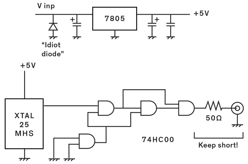
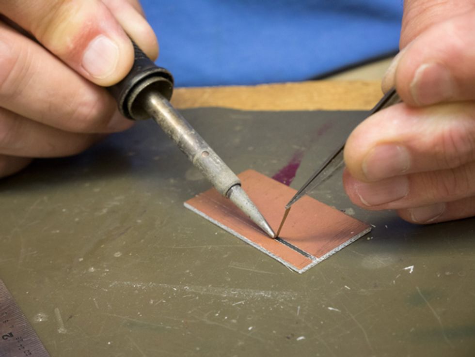
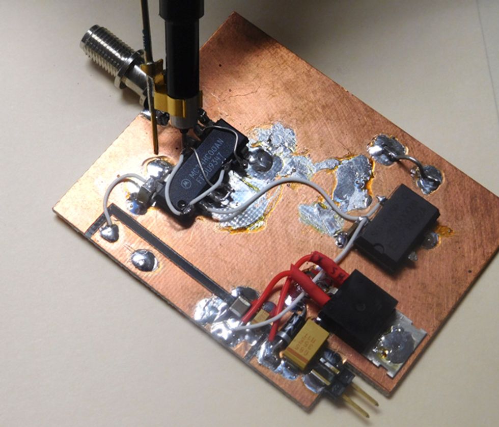 Figure and Ground: The comb generator uses NAND gates to create high-frequency pulses (top). To implement the circuit, I remove copper from the board (middle) to create a power rail and ground plane (bottom).Photos: Robert Melville
So I began thinking about practical alternatives for high-frequency circuits that can provide maker-friendly prototypes that are fast to build, and easy to probe and alter. In this article, I'll be presenting one key idea; some follow-on strategies will appear on the IEEE Spectrum website in the coming weeks. I should say that I make no claims of originality: Indeed I employ some oft-forgotten, decades-old techniques, but they turn out to be surprisingly useful in an age of surface-mount components operating at gigahertz frequencies.
The general approach is to start with a standard raw board, typically one made using FR4-grade resin, with its copper layer untouched. Instead of using etched traces, you interconnect components with lead wires while leaving a large ground. To demonstrate, I built a so-called comb generator circuit.
A comb generator produces a set of sharply defined harmonics across a wide range of frequencies, in this case up to 1 gigahertz, and it is a useful building block in microwave systems. The heart of my generator is a 74HC00 integrated circuit [PDF], which houses four NAND logic gates. A signal from a 25-megahertz surface-mount generator feeds two of the NAND gates in series so as to produce two square-wave signals that are slightly delayed. These signals go to a final NAND gate that generates narrow “sliver" pulses, which form the harmonic spectrum.
To create a circuit, I divided the copper layer into two lands. In this case, I wanted one small area along the top to serve as a 5-volt supply rail. Everything else forms the ground plane.
To isolate the lands from each other, I stripped off three thin rectangles of copper to form the boundary of the supply rail. I did this by marking parallel lines with a scriber. Then I held a steel ruler very firmly against the scribe marks and used a hobby knife to cut all the way through the copper along the length of the rule (this takes a fair amount of force, and often several passes). Then, using my soldering iron to heat the copper between the lines, I peeled each strip away using tweezers.
So how do you mount an integrated circuit on a board that's mostly a single ground plane with no through holes? You bend the IC's ground pins back so that they touch the surface, and solder them to the ground plane, holding the IC in place. You bend the other pins parallel to the board and solder connecting wires directly to them. Sometimes this is referred to as the “dead bug" method because of the way ICs look with their legs sticking out. As a bonus, the dead-bug method makes soldering surface-mount components easier than with a conventional PCB, as the contacts are more accessible. The ground plane also provided a convenient place to attach the heat sink of my comb generator's power regulator.
With a bit of practice cutting and peeling strips from the copper layer, it is possible to form an isolated land in the middle of a board to act as a tie point for both surface-mounted and through-hole components. Such an isolated land has very little capacitance to ground.
Another advantage of this construction technique is that you can easily check if your high-frequency circuit is in fact working as designed. Using a spectrum analyzer with a 500-ohm resistive probe (such as the Tektronix P6056) works well for such circuits, as long as the probe's shield is connected to ground close to the circuit node being probed. By attaching a spring-mounted Pogo pin to the probe's ground shield that extends down to the board, I'm able to make a ground connection right beside whatever pin I'm touching the probe to. (If you can't find a P6056 or similar probe, you can make one yourself using a 450-ohm resistor in series with a 50-ohm length of coaxial cable, but remember to use a 50-ohm terminator at the analyzer end.)
The results of these methods are not always the prettiest-looking boards, but I've had good success in using these techniques to prototype microwave circuits. I hope you'll follow me online to see some further elaborations of the ground-plane method, along with some other tips and tricks that I and some of my fellow circuit builders have been using for high-frequency circuits.
This article appears in the October 2018 print issue as “Resurrecting the “Dead Bug" Method."