
I am a member of a team at IBM Research–Europe, in Zurich, developing microfluidic technologies for medical applications. Two years ago, I was asked to provide high-quality photos and videos of our microfluidic chips for a big tech event. I borrowed a 4K camcorder from a colleague, attached a macro lens to it, built a custom light diffuser using an LED matrix and polyester film, and positioned everything using a high-end tripod and a few micromanipulators. I was able to take eye-catching videos as liquids filled microfluidic channels. It was clear to me that this should be the new level of quality and style for our publications and presentations. However, my photo setup occupied half a bench in our lab and it required hours of fine adjustments to record one shot.
We have a tradition of inventing microscopes at IBM in Zurich. In 1981, Gerd Binnig and Heinrich Rohrer created the scanning tunneling microscope here. As a DIY enthusiast, I quickly found myself in my own quest to build a better setup. The result was a US $300 modular and motorized microscope that combines my three favorite adulthood hobbies: Arduino, Raspberry Pi, and Lego.
Taking a photo of a microfluidic chip is not easy. The chips are typically too big to fit into the field of view of a standard microscope, but they have fine features that cannot be resolved using a regular camera. Uniform illumination is also critical because the chips are often made of highly reflective or transparent materials. Looking at publications from other research groups, it’s obvious that this is a common challenge. With this motivation, I devoted some of my free time to designing a multipurpose and compact lab instrument that can take macro photos from almost any angle.
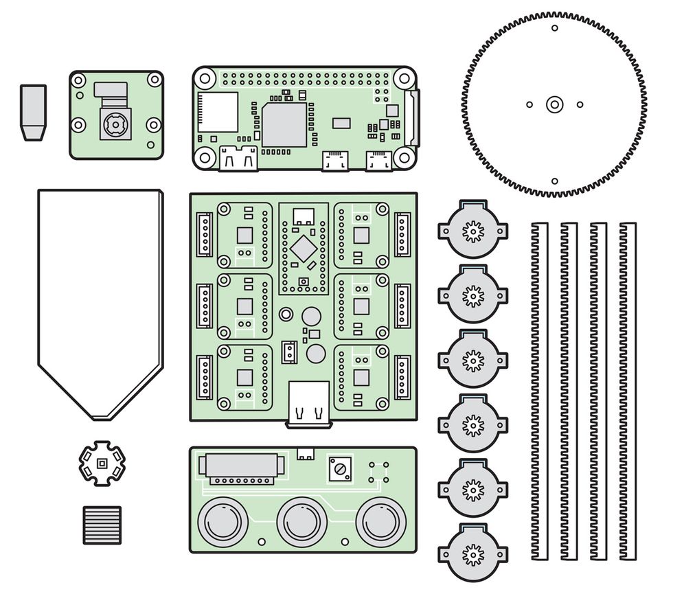 Mixed Materials: The imaging microscope design uses a potpourri of technologies and materials, including Lego pieces for its main structural components and 3D-printed cogs and racks to drive its moving parts. Stepper motors, which allow for precise movements, are powered by a motor driver board and controlled by an Arduino board. A Raspberry Pi Zero and Pi camera module are used to capture images. The original design incorporated custom-made control boards and parts printed on a high-resolution printer, but prior to public release the microscope was redesigned to be assembled with off-the-shelf boards and parts that could be printed on less expensive, low-resolution printers.Illustration: James Provost
My first prototype was a Raspberry Pi camera module mounted on a stage that could be moved in three dimensions using the mechanisms of linear stepper motors from old CD-ROM drives. The Raspberry Pi camera was an ideal choice because it allows the manual adjustment of critical parameters like ISO settings and exposure time. I carefully removed the plastic casing holding the lens, revealing the CMOS image sensor, and engineered a delicate mechanism to move the lens back and forth in fine steps so I could take high-magnification macro photos. The setup worked well for a while, but it was fragile. I broke the lens mechanism and damaged the image sensor several times by accidentally forcing the moving parts beyond their limits.
I decided to take a different approach. I removed the lens entirely from the Pi camera. Then I took the objective lens from a low-cost USB microscope and mounted it on another CD-ROM linear actuator so that the objective lens could move back and forth along the optical axis of the Pi camera. I built a housing from Lego bricks to shield the camera’s exposed sensor.
However, this attempt resulted in nothing but an appreciation of the high price tag of the linear stages used in microscopes: The travel distance of the CD-ROM actuator was too short to achieve a wide magnification range.
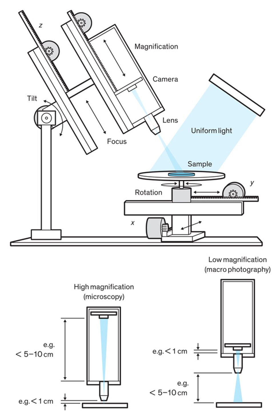
I switched to a lead-screw mechanism used in 3D printers. Instead of commonly used 8-millimeter-diameter threads, shafts, and bearings, I used 3-mm-diameter components to keep things compact. Also, moving the objective lens caused problems in eliminating stray light, so I decided to move the camera sensor instead. I built a stage that allowed the object being imaged to be moved along the x and y axes and rotated. In total, I wound up with six miniature stepper motors with gearboxes that allow me to move the stage, tilt the microscope, adjust its distance to the object, and focus the image.
I often design my own Arduino boards for a more compact implementation. This time, I designed a board measuring 18 by 18 mm and featuring an ATtiny84 microcontroller and a DRV8834 [PDF] stepper-motor driver. The setup gave surprisingly good image quality, for not only beauty pictures of chips but also for examining features with dimensions of a few micrometers, and even as a digital goniometer for measuring contact angles. I had started the project for a specific need, but it became clear to me that this could be a multipurpose imaging system that anyone can assemble and use at home or school.
loyaltyshopping_cartlocal_librarydelete
IBM and my managers supported me in publicly sharing the assembly instructions. However, as I prepared the instructions for public releases, several issues started bothering me. I had built everything using a state-of-the-art 3D printer and a fully equipped mechanical workshop. Also, the small stepper motors I used were expensive and not available in popular hobby electronics stores. Programming the ATtiny84 via a dedicated ISP programmer was certainly not as easy as programming commercial Arduino boards with a USB port. I went back to the drawing board and redesigned everything using easily accessible components, for example Arduino boards and stepper-motor drivers from Adafruit Industries, and 28BYJ-48 stepper motors, which can be found anywhere for a few dollars. I also replaced the LED-matrix light source with a more maker-friendly and lower-cost version. I bought an LED backlight module from Adafruit for $3 and attached a high-power LED. The intensity was slightly lower than that of the original LED matrix but the uniformity was pretty good for both reflected- and transmitted-light microscopy. For the new linear actuators, I combined “sliding” pieces from Lego with a rack-and-pinion gear combination that I designed using FreeCAD’s gear toolbox and printed using my personal Creality Ender 3 Printer. The new design worked as well as the previous one, if not better.
There are probably still many things that could be improved, and I hope this prototype persuades other makers to try new and better ideas. Could it replace a laboratory microscope? Maybe not, but it’s a great solution for budget-constrained schools, which is why we have made the instructions open source for everyone to access and enjoy.
This article appears in the May 2020 print issue as “The Lego Microscope.”


