Like vinyl and cassette tapes, cathode ray tubes are experiencing a comeback in some circles. Retrogamers want to experience old titles on the fuzzy displays they were designed for. And makers have been deconstructing them for all kinds of projects: In January of 2020, we featured a vector graphics clock based on a CRT originally made for an oscilloscope. But oscilloscope CRTs are relatively rare, while old analog television sets can literally be found littering sidewalks. So when I came across a cheap listing on eBay for a portable black-and-white television with a 5-inch-screen that looked in almost mint condition, I thought I'd take on the challenge of tackling this old technology.
Unlike with an oscilloscope CRT, you can't easily control a television CRT's electron beam directly. Instead, it's best to feed in a video signal that the original circuitry can decode. So I decided to make a Geek TV: Instead of broadcast channels, it would display the latest updates and imagery from places like NASA and the European Organization for Nuclear Research (CERN), as well as some animations. And I wanted it to reflect the original TV's self-contained simplicity: no extra cables or boxes dangling off it and certainly no keyboard, mouse, or extra switches for control.
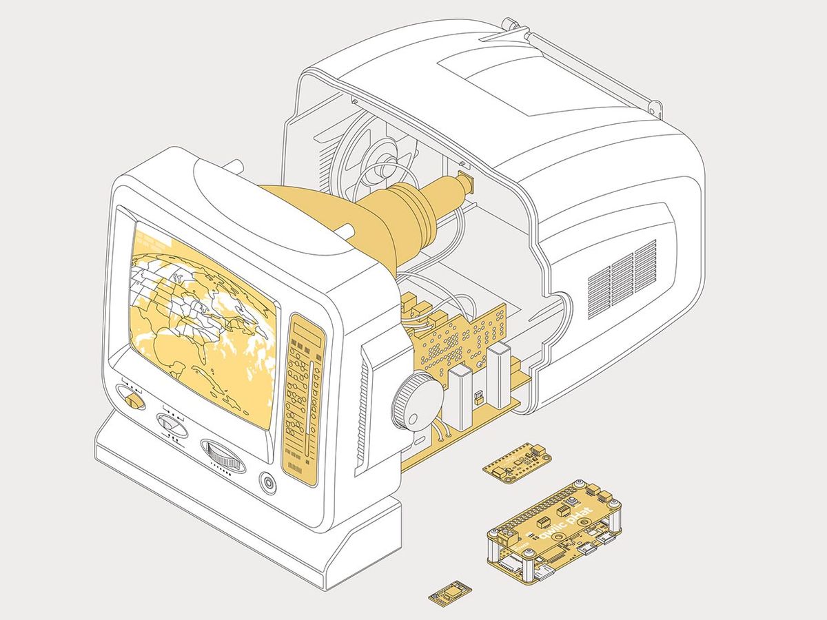
My “new" TV is a Coby CX-TV1, which has an RCA composite video connector and runs off a DC power supply adapter, both of which suggested I would have good jumping off points in the internal circuitry for hacking.

Once I unscrewed the case and looked at the guts, I was even more encouraged. The internal circuitry is divided into two parts: a main printed circuit board built around a clone of an AN5151 chip, and a secondary PCB mounted at a right angle. The TV's tuning knob turns the shaft of a variable capacitor on this secondary board.
I had always planned to use this side-mounted knob as my control for selecting “channels," but initially I thought I would mount it to a rotary encoder to detect movement. But once I saw how the PCBs were arranged, I had one of my rare moments of inspiration. I disconnected the tuner board from the main PCB, and hooked up one of the leads of the variable capacitor to an Adafruit MPR121-based touch sensor.
This capacitive sensor is intended to provide a simple yes/no response to the question of “Is a finger touching a surface or not?" But by looking at raw sensor measurements, I could determine the variable capacitance, and thus the knob's position. As a bonus, this meant I could leave undisturbed the cute mechanical mechanism that moves a red plastic strip up and down to indicate the channel the TV is tuned to.
I added brains to the TV with a Wi-FI-enabled Raspberry Pi Zero W that I had lurking at the bottom of a drawer. (If I was starting from scratch, I would probably use a Pi 3 or 4 compute module for faster processing, but I was happy to put the Pi Zero to good use.) Every Pi has the ability to generate composite video in NTSC or PAL format. In the Pi Zero's case, an unpopulated socket provides the signal, so it was a few moments' work to solder in a header. A little bit more soldering work let me run wires from the header to the back of the TV's RCA connector. As my TV is black and white, I disabled the composite video's colorburst signal in the Pi's configuration file for a slightly sharper image.

The only major hardware step remaining was the power supply: Most of the TV's internal circuitry runs at 12 volts, which would immediately fry the Pi, so I used a buck converter to step down the voltage to 5 V. Two more dabs of solder connected it to the TV's on/off switch and ground.
I wrote the software in Python: A passel of libraries makes it easy to tie together the hardware with higher level routines for extracting and processing images from online sources. First, I installed Adafruit's Blinka bundle—which is a backport of Circuit Python, originally developed to squeeze Python into microcontrollers. With Blinka, I can communicate with my touch sensor via an I2C connection mounted on a SparkFun Qwiic pHat v2.0 board plugged into the Pi's GPIO header. (The pHat also provides a convenient pair of screw terminals connected to the Pi's 5-V and ground rails that lets me bring the power in from the buck converter).
Getting imagery from online sources requires a combination of techniques. For example, the status dashboard of the Large Hadron Collider at CERN is displayed as a PNG that's always found at a static URL. The Pi just has to download the image and scale it to the 720-by-480 resolution of NTSC composite video. Another channel on my Geek TV displays NASA's Astronomy Picture of the Day. To download this, the Pi has to query an API that returns metadata, and then parse it using a JSON library to get the URL of the daily image. And getting the latest photo from the GOES East weather satellite means parsing HTML using the Beautiful Soup library.
I also added some animations: One channel “plays" Conway's Game of Life. Another channel cranks out increasingly higher resolution versions of the Mandlebrot set. And in between channels, the TV displays pixelated “static."
To finish up, I had to repair some leads to the CRT that had broken because of all the flexing that had happened while I was soldering in new connections. Once this was done, it was just a matter of stuffing everything inside the TV case and closing it back up. Now, to get my latest science updates, all I have to do is turn on and tune in.
This article appears in the May 2021 print issue as “Geek TV."
Stephen Cass is the special projects editor at IEEE Spectrum. He currently helms Spectrum's Hands On column, and is also responsible for interactive projects such as the Top Programming Languages app. He has a bachelor's degree in experimental physics from Trinity College Dublin.


