
Digital technology continues its march from media like CDs and DVDs toward your audio speakers. Today, amplifiers based on digital principles are already having a profound effect on equipment efficiency and size. They are also beginning to set the standard for sound quality.
An old idea, the Class D amplifier has taken on new life as equipment manufacturers and consumers redefine the musical experience to be as likely to occur in a car, on a personal stereo, or on an airplane as in a living room. For most consumers today, portability and style outweigh other factors in the choice of new audio gear.
Class D amplifiers are ideally suited to capitalize on the trend. They are already starting to displace conventional high-fidelity amplifiers, particularly in mobile and portable applications, where their high efficiency and small size put them in a class by themselves. For example, they are fast becoming the dominant technology for entertainment systems in cars, where passengers are now apt to watch a DVD—and expect from the vehicle’s compact, ill-ventilated electronics the same rousing surround-sound experience they get at home.
The new amplifiers can provide it. They are typically around 90 percent efficient at rated power, versus 65-70 percent for conventional audio amps. Such high efficiency means, for one thing, that the amplifiers can get by with much smaller heat sinks to carry away the energy they waste. Also, portable devices like MP3 players can go much longer on a battery charge or can be powered by tinier, lighter batteries.
Class D amplifiers have been used for decades in industrial and medical applications when high efficiency is key. They have been applied with great success in devices as small as hearing aids and as large as controllers for hefty motors and electromagnets. They blossomed as a significant force in high-fidelity audio a few years ago, when Class D power amplifier chips were released by companies like Tripath Technology, Texas Instruments, and Cirrus Logic in the United States; Philips and STMicroelectronics (partnering with ApogeeDDX) in Europe; and Sanyo (partnering with Bang & Olufsen) in Japan.
More recently, Class D amps have expanded beyond the hi-fi niche, showing up in MP3 players, portable CD players, laptop computers, cellphones, even personal digital assistants (PDAs). At the same time, they have been making forays into the world of home audio in the form of products based on those new chips. Notable entries include amplifiers from Bel Canto Design Ltd. (Minneapolis, Minn.) and PS Audio (Boulder, Colo.). Sharp Corp. (Osaka, Japan) is also pushing aggressively into the home audio market with a somewhat different line of amplifiers ranging in price from US $500 to $15 000. The company uses sigma-delta modulation, which has the effect of limiting the amplifiers’ efficiency.
By the way, the “D” in Class D does not stand for digital, but was simply the next available letter for classifying amplifiers. What distinguishes Class D amplifiers from all others is that their power transistors are always operated either fully on or fully off. This is the only and complete definition of Class D; its significance will become clear later.
Nomenclature aside, Class D amps do point to an eventual sea change for audio. In their most obvious form, these systems will be able to accept a stream of bits from a CD or MP3 player and convert it into an analog signal that can drive a set of speakers. Contrast these with conventional amplifiers, which are entirely analog and can amplify digital signals only after those signals have been converted into analog form, usually in the CD player or MP3 unit figure].
Class acts
Today, Class D amplifiers generally work with low-level analog signals, which they pump up to current and voltage levels high enough to drive audio speakers. Remarkably, the heart of such an amplifier does this by switching between only two signal levels. That feat is achieved through various pulse modulation schemes, in which a continuously varying analog waveform is changed into one that switches between just two values—a binary signal, in other words. Some parameter of this binary signal—for example, the relative duration of its on- and off-states—conveys the same information contained in the smooth curve of the analog input wave [see illustration]. Before delving more deeply into the workings of this scheme, called pulse-width modulation, let’s briefly review conventional amplifier circuitry.
Engineers have divided amplifier circuit types into different topologies and classes, depending on how much current is allowed to flow through the transistors or tubes when they aren’t delivering power to the speakers. Most conventional audio amplifiers are a variation of a topology known as push-pull. In its most elementary form, it uses two transistors (or, if you prefer, vacuum tubes): one for pushing current, or sourcing it, toward the speakers; the other for pulling it back, or sinking it. To get a (very) rough idea of how it works, think of two lumberjacks sawing a tree, one on either end of a long, old-fashioned saw.
In Class B push-pull, output current is delivered by only one transistor at a time, while the other is completely inoperative. In the case of the lumberjacks, only one could be pushing on the saw at any given instant—and they would have to time their exertions very precisely to work efficiently. Similarly, in a Class B amp, note that all of the output current [green waveform] comes either from the current-sourcing transistor [red waveform] or from the current-sinking one [blue waveform] but never from both at the same time. This mode of operation is rather efficient: it can theoretically deliver 78 percent of the power it receives from the power supply to the speakers, dissipating the rest as heat.
In this kind of amp, 100 percent of the current that goes through the transistors is delivered to the speakers. So why isn’t the amplifier 100 percent efficient? Recall that power is the product of current and voltage. If our amplifier has a maximum output voltage of, say, 40 V, and at some point is called upon to put out, say, 8 V across the 8-ohm speakers, the output current would be 1 A and the output power would be 8 W. But since the supply voltage would have to be 40 V to properly handle higher instantaneous voltages, at that instant 32 V would be dropped across the transistor while the very same 1 A of current flowed through it. The result: 40 W of power consumption—8 W to power the speaker and 32 W to heat the room.
The main problem with Class B is crossover distortion, which occurs when operation switches from one transistor to the other. If this instantaneous switching of the two devices is not coordinated with absolute perfection, the discontinuity creates distortion that can be heard in the sound coming out of the speakers.
So for audio, engineers prefer Class AB amplifiers; you almost certainly have one in your home. In Class AB, both transistors carry current even when no net current is delivered to the load, doing so at what is known as the crossover point. Remember our lumberjacks sawing the tree. Class AB operation frees them from the restriction that they may push only one at a time. Now one lumberjack can begin pushing before his partner has finished his stroke. The result is lower efficiency (because they are actually fighting one another) but a smoother transfer of the workload from one man to the other as the first one pushes less and less hard and the second one gradually takes over.
So it is with transistors. Unlike Class B, in which one transistor must turn off at precisely the time the other one turns on, Class AB allows operation to hand off gradually from one transistor to the other. In the diagram, note that at point A on the waveform, all of the [green] output current comes from the sourcing transistor [red], and the sinking transistor is off. At point B, the sinking [blue] transistor starts to conduct, diverting some of the source current from the load. By the time the output current drops to zero [at point C], all the source current is diverted to the sinking transistor. Beyond that point, the sinking transistor carries more current than the sourcing one, and there is again net current through the load—but in the opposite direction.
Compared with Class B, Class AB exhibits less distortion because it doesn’t require that one transistor turn on precisely when the other turns off. But it is also less efficient because, in the crossover region, when the output current is near zero, some current flows from one transistor to the other and never gets to the load at all.
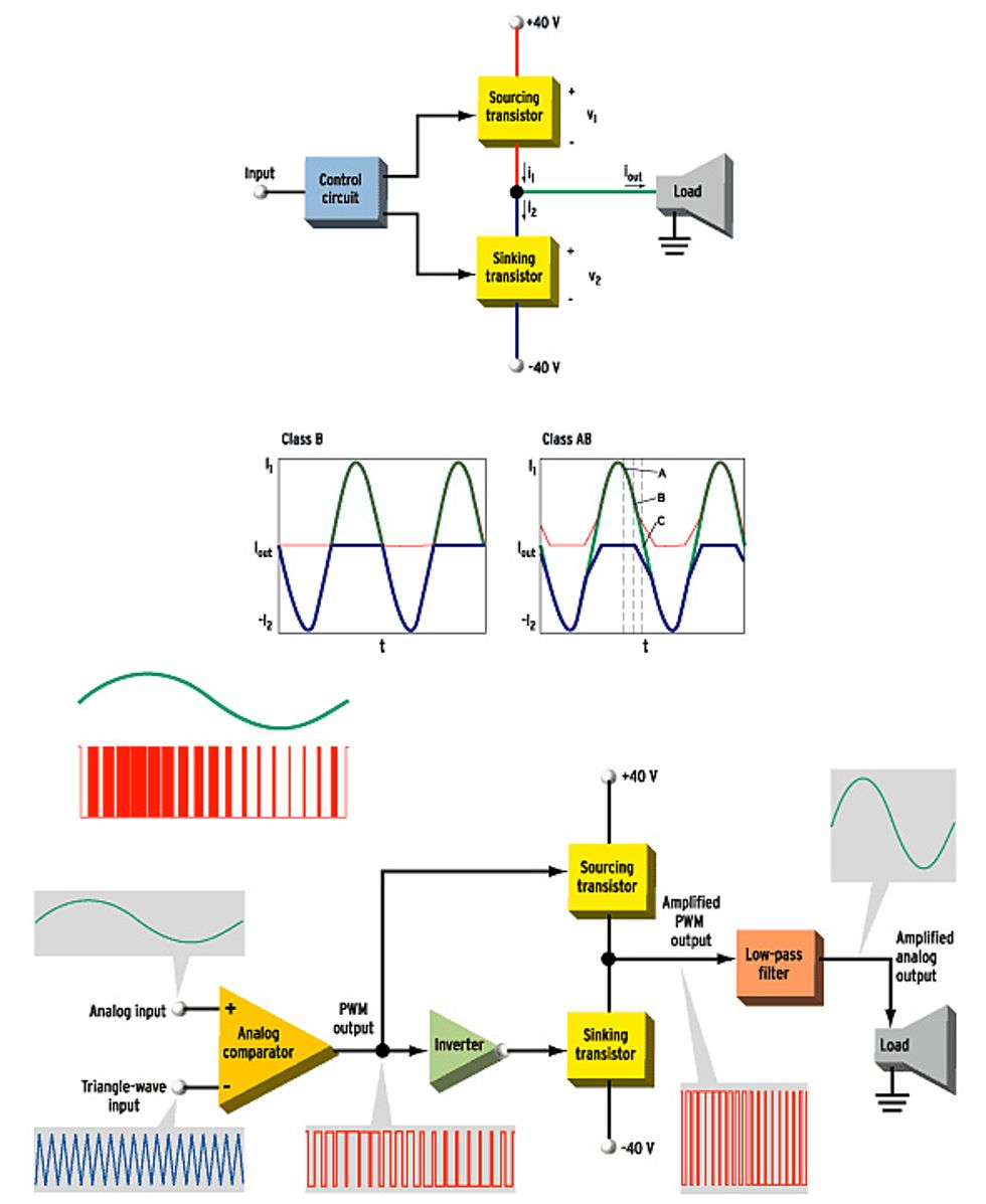
One way to get a two-state, on-or-off, amplifier to handle analog audio signals is through the use of pulse-width modulation (PWM), which converts the audio input [green] into a binary PWM signal [red] by comparing it with a triangle waveform [blue] as shown in the circuit diagram [below]. The PWM signal turns the sourcing power transistor on and off, while its inverse does the same for the sinking power transistor. The gain of the amplifier is varied by varying the value of the ±40-V supply voltages.
The red waveform below carries all the information in the green analog signal by spending, on average, more time at its upper value when the analog signal is larger and less time there when it is smaller. [ Click on the image for a larger view.]
The powers that “D”
Class D amplifiers also use two transistors, but instead of amplifying analog signals, which can assume any value, they switch between just two voltage values, +40 V and -40 V in the case of the amplifier mentioned above. One transistor can connect the output to the +40-V rail, the other to the -40-V rail.
Theoretically, neither transistor wastes any power. When one is turned fully on, all of the power supply voltage is dropped across the speakers and none drops across the transistor. When it’s fully off, all of the supply voltage drops across the transistor, but no current flows through it. In both cases, the product of the voltage across the transistor and the current through it is zero.
Of course, this Class D amplifier can reproduce only binary (two-valued) waves. So to use it to amplify analog music signals, those signals have to be converted into a suitable on-off waveform. One way to do this is with pulse-width modulation (PWM). In PWM, the amplitude of an analog input signal serves to control the average percentage of time the transistor spends turned fully on, known as its duty cycle.
The PWM signal is generated by comparing the analog input signal with a triangle waveform—one that continuously sweeps linearly from a low to a high value and back again. To do that, both signals are fed into an analog comparator whose output is high whenever the analog signal has the higher instantaneous value, and low when the opposite is true.
The output of this analog comparator, then, is a waveform that has the information of the original analog signal and yet switches between just two values—in other words, it’s precisely what we need. In a Class D amplifier, this PWM waveform acts as a binary control signal that switches the transistors on and off depending on the amplitude of the analog input. Changing the power supply voltages changes the amount of amplification.
Of course, what the transistors produce is a higher-power version of this same, switching waveform, which would overheat the speakers dreadfully if allowed to reach them, containing as it does amplified versions of both the original audio input signal and inaudible higher-frequency components arising from the PWM process. So after the amplification, that PWM wave has to be passed through a filter that lets lower-frequency signals through while weakening the higher-frequency ones. This the low-pass filter does by smoothing the switching waveform, in effect suppressing the rapid changes in the output waveform and leaving only its average value. At the same time, happily enough, it filters out noises caused by the switching process itself.
Class D audio amplifiers are reasonably simple, conceptually. The trick is building one that is affordable and that performs well. First of all, it requires inexpensive, low-loss, fast-switching transistors that are easy to drive. Such devices became available only with the maturing of metal-oxide semiconductor field-effect transistors (MOSFETs) in the early 1990s [see “The Once and Future Audio Amplifiers”].
D for distortion
Second, Class D designs are prone to distortion, chiefly from imperfect power supply regulation and timing error. Since the output voltage of a Class D amplifier is directly proportional to the power supply voltage, any error in that voltage modulates the output voltage. Power supply variations caused by variations in the amount of current drawn by the amplifier show up in the output as distortion. Instabilities in the supply itself, such as power line ripple, show up at the output as noise, or hum. Building a power supply so that voltages remain rock steady in spite of fluctuations in output current is not a trivial task.
The other source of distortion is timing error, due to variation in how long MOSFETs take to switch from on to off, which in turn depends on how much current the amp is being called on to deliver. This error causes the output duty-cycle to deviate from the input duty-cycle, such that the output signal’s shape differs from the input signal’s shape. Timing error causes distortion directly proportional to the duty-cycle error—the ratio of the timing uncertainty to a single switching period. The greater the timing uncertainty and the higher the switching frequency (the higher the frequency of the triangle wave in the PWM circuitry), the worse the distortion.
Future digital amps will include digital signal processors to correct the power stage’s inevitable analog errors
An IC power stage optimized to minimize its timing uncertainties, like the one from Texas Instruments, can sport errors as low as 10 ns. With a typical switching frequency around 350 kHz, this corresponds to a distortion figure of around 0.1 percent. Such figures are certainly acceptable for inexpensive multichannel audio. But high-performance audio amplifiers for items such as MP3 players and home stereos need to reduce distortion to as little as 0.01 percent. Fortunately, it’s possible to correct for this rather inexpensively.
Frequency response is another prime performance issue for Class D amplification. The all-important low-pass output filter, which recovers the original audio signal from the PWM waveform, is passive, and its frequency response is flat only when it drives a purely resistive load of a specified value. Since the impedance of real loudspeaker loads varies between 4 and 16 ohms at various frequencies, a solution is obviously needed.
These performance issues persuaded many engineers to adopt a stance of technical conservatism that delayed the commercial introduction of Class D amplifiers for many years. But practical demonstrations and listening tests have revealed that amplifiers encumbered with these deficiencies were more pleasant to listen to than the performance figures alone suggested.
Because modern signal sources are digital, it seems natural to derive the PWM signal directly from the digital source, without converting it to analog first. Indeed, the early 1990s saw the development of several schemes for converting the digital outputs of equipment like CD and DVD players into PWM waveforms suitable for driving switching power devices. Their development reflected a belief that digital-to-analog (D-A) conversion incurs quality loss and that D-A converters are necessarily expensive.
Obviously, both premises are relative. As noted earlier, an output stage driven directly by a PWM signal is unlikely to yield harmonic distortion figures much better than 0.1 percent—and it needs an expensive regulated power supply to do even that well. Digital PWM generators are presently available, but only as fairly expensive stand-alone chips. Currently available D-A converters easily deliver harmonic distortion as low as 0.01 percent for as little as US $0.50 per stereo chip.
Feedback is key
The three major problems confronting high-resolution Class D operation (power supply modulation, timing errors, and load-dependent frequency response) can be cheaply and effectively solved using an analog feedback system. Several varieties of these are available, all of them compensating for output-stage distortion and some addressing the frequency-response problem as well.
Other benefits accrue, too, including more relaxed settings for the power-stage timing, which increases efficiency, electromagnetic compatibility, and economy. Currently, several analog Class D amplifiers are available (from Piak Electronic Design, Philips’ UCD, and Bang & Olufsen, among others) that readily compete with the traditional strengths of the best linear amplifiers: low harmonic distortion and low output impedance. Some of these amplifiers are frighteningly simple in construction, consisting of no more than a handful of discrete parts.
This notion—that a partially analog approach may be the best way to realize a “digital amplifier”—may be hard to swallow in this increasingly digital world. In light of the following, though, the idea may become more acceptable:
- Loudspeakers are analog and the basic technology behind them dates back to the first half of the 19th century. We may have to develop a vastly different loudspeaker technology, one somehow more inherently digital, before wholly digital power trains come into their own.
- Even highly digitized devices typically include analog technology. Cellphone transmitters, for instance, employ linear amplifiers, even though the modulation is digital up to that point.
- Switched power stages’ unwanted effects are analog in nature; minimizing them requires highly developed analog engineering.
- Digital Class D is still in its early infancy—it’s not fair to expect the digital amplifier to deliver the whole package, yet.
- Today’s dilemma comes down to a choice between low-cost, high-performance analog solutions and future-oriented, more costly, in a word, embryonic, digital ones. It’s only a matter of time before there will simply be no need for such a choice.
Growing up
In spite of its current deficiencies, digital Class D amplification is already well on its way to ascendance. Multimedia devices and miniaturized home-theater-in-a-box systems have no strong requirements for high-resolution audio performance, although many do have system-integration and miniaturization imperatives.
Future research efforts in digital amplification will increasingly focus on integrating digital signal processing (DSP) to correct the power stage’s inevitable analog errors. Several companies are already well down that path, building controllers that sense the power rail voltage and modify the PWM signal accordingly.
The distant future will almost certainly witness circuits that perform digital modulation on the fly by measuring analog error data from the power stage and modifying the switch control signal accordingly. Preliminary work from several researchers suggests that such schemes may ultimately deliver performance that is simply out of the question any other way.
About the Author
Bruno Putzeys is chief engineer, Class D audio, at Philips Digital Systems Laboratories in Leuven, Belgium. He has designed linear and Class D power amplifiers, digital and analog noise shapers for analog-to-digital and digital-to-analog conversion, and microphone preamplifiers. He holds several patents in Class D amplification and digital audio.
To Probe Further
The Web site at https://www.classd.org offers technical details and evaluations of various Class D technologies and products.
For specifics on Philips’ completely integrated Class D amps—the most powerful around—see https://www.semiconductors.com.
Visit https://www.ti.com to learn about Texas Instruments’ strong portfolio of analog and digital Class D products.
Home of the world’s first fully integrated Class D amp, STMicroelectronics has a site at https://www.st.com.
Tripath’s Class D chips and drivers incorporate some nifty tricks borrowed from analog-to-digital and digital-to-analog converter design. Check them out at https://www.tripath.com.