The following is an excerpt from Multiphysics Simulation 2017 .
At the European Organization for Nuclear Research (CERN), located near Geneva, Switzerland, physicists and engineers conduct experiments that aim to answer fundamental questions in particle physics and about the origin and nature of our universe.
Inside the Large Hadron Collider (Figure 1), a 27-km long underground particle accelerator that extends across the border between France and Switzerland, two particle beams traveling nearly at the speed of light in opposite directions are set to collide. The results of experiments involving high-energy collisions drive our understanding of the fundamental forces and the most basic constituents of matter.
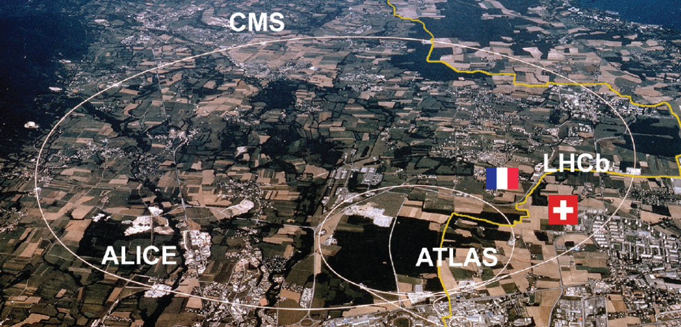 Figure 1. Map showing the location of the LHC tunnel across France and Switzerland.
High-field dipole magnets, operated at currents as high as 12 kA and reaching magnetic fields of 8.33 T, allow for maintaining the circular trajectory of the particles inside the LHC. The magnets (Figure 2) are cooled down to 1.9 K, colder than the temperature of outer space, to maintain the magnet cables (Figure 3) in the superconducting state. This, in principle, allows the current to continuously circulate in the magnet coils without resistive losses. However, in practice,portions of the magnet coil may revert to a resistive state at times.
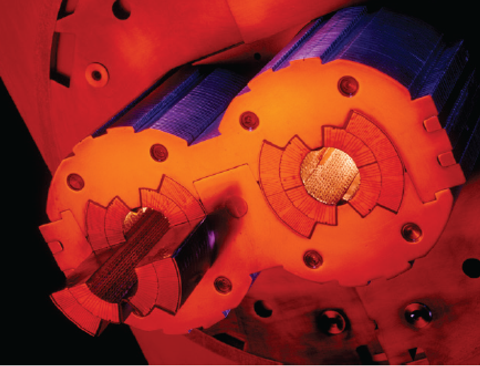 Figure 2. Detail of the main dipole aperture. The superconducting coils are kept in place by means of austenitic steel collars to counteract electromagnetic forces of 2 MN/m per coil quadrant at nominal field.
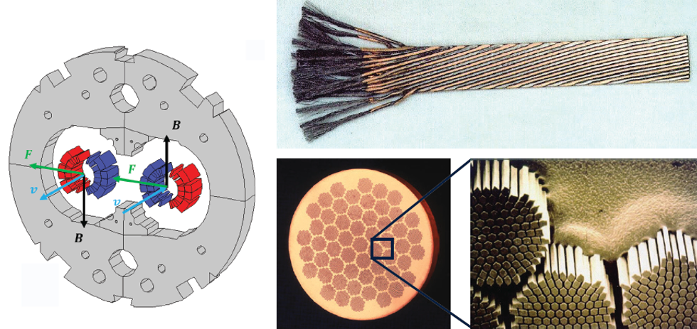 Figure 3. Left: A cross section of the LHC main dipole. Red and blue domains represent the superconducting coils keeping the particles in a circular trajectory. The gray domain represents the iron yoke. Right: High-current superconducting magnets in the Large Hadron Collider are based on cables made of superconducting microfilaments embedded in a copper matrix.
This can occur due to a local temperature increase caused by mechanical movements, AC losses, or losses from the circulating high-energy proton beams. The latter continuously occurs along the machine circumference, when particles deviate from their ideal trajectory and impact on surrounding accelerator equipment such as the magnets. If the energy deposited by the impact is large enough, this causes a sudden, local transition in the coil material from the superconducting to the normal conducting state, known as a quench. The superconducting state of the material is defined by its “critical surface”, which is determined by the critical temperature, electric current density, and magnetic field seen by the superconductor (see Figure 4). Transitions beyond the “critical surface” cause the transitions from superconducting to resistive state and give rise to magnet quench.
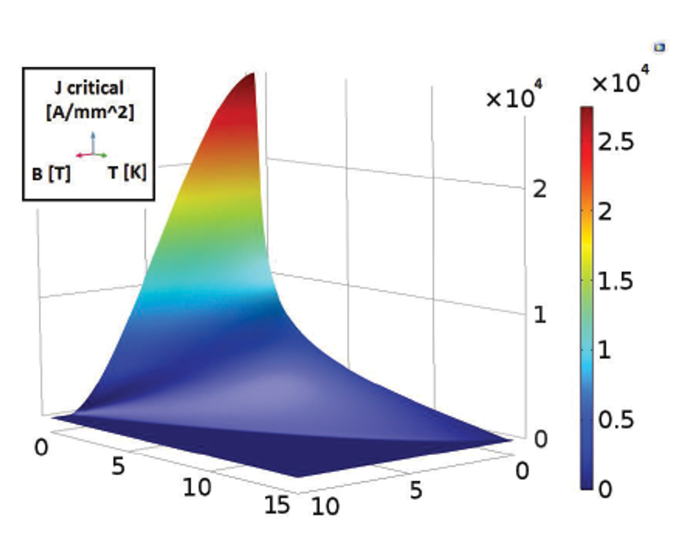 Figure 4. Critical surface for the Nb-Ti superconducting material of the magnets.
The resistive state associated with a quench leads — if no protective actions are taken — the dissipation of all of the electromagnetic energy stored in a limited volume of magnet coil. In a single LHC dipole magnet, around 7 MJ of energy is stored, enough to melt more than 10 kg of copper. Megawatts of power could potentially be dissipated in the coils, resulting in large thermal gradients. It is worth noting that the energy stored in all 1232 LHC main dipoles is about 9 GJ, comparable to the energy stored in 1.5 tons of dynamite. In the unlikely event of an unprotected quench occurring at nominal energy, high-field accelerator magnets will very likely be severely damaged beyond the possibility of repair. The replacement of a faulty magnet would take up to several months, severely impacting machine availability, since no beam operation would be possible.
Lorenzo Bortot, electrical engineer and research fellow at CERN, worked on the development of a 2D finite element, electrothermal representation for superconducting magnets. He develops time domain studies, suitable for assessing the performance of the newest technological solutions for the automated quench response systems.
DETECTING THE QUENCH
During the normal operation, the magnets are mostly at a steady state, and their field (Figure 5) guides the particles through the LHC. The coils are superconducting, so the measured voltage drops across the magnets are equal to zero, and almost no Joule losses are observed. Dedicated electronic systems monitor the magnets and react quickly to the sudden presence of a resistive voltage drop across a coil or between neighboring magnets. Once the signal exceeds a certain voltage threshold for a minimum validating time, the quench detection system will trigger protective actions.
Not only must the protection system be properly designed and adapted to the supervised magnet, but the electronics must be properly configured and optimized. On one hand, the detection system must be kept sensitive enough to not miss any quench event. On the other hand, applying unnecessarily strict criteria could potentially lead to false alarms. These would result in the interruption of LHC operation and undesired downtimes up to several hours, reducing the machine availability.
PROTECTING AGAINST QUENCH
The Magnet Quench Protection System exploits a simple yet effective strategy: Spread the quench along the entire magnet to maximize the volume where energy gets dissipated, instead of allowing only a fraction of the magnet to absorb all of the stored energy.
“We heat the magnet itself up to increase the size of the normal conducting zone and dissipate the energy stored in the magnet over the entire coil volume,” Bortot explained. “This trick is counterintuitive: As long as the magnet is in normal operation, we want it as cold as possible to maintain its superconducting state — but if a single point fails, we then need to heat up the entire magnet as quickly as possible. Homogeneity is key.”
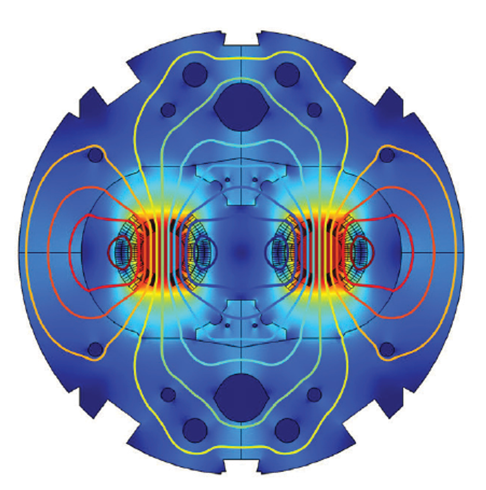 Figure 5. A model shows magnetic fields in the magnet with nominal current applied during its superconducting state.
A novel yet very promising technology for quench protection recently developed at CERN is called the Coupling-Loss Induced Quench system (CLIQ). Its main component is a charged capacitor bank connected in parallel to the magnet’s coil. When enabled, it introduces an LC resonance, forcing an oscillation of the magnetic field within the magnet.
This in turn induces the coupling and eddy currents in the cable, including at the level of the filament structure. The coil heats up from the inside in a very uniform way, in a process analogous to microwave heating. The aim of CLIQ is twofold: maximize the volume over which the eddy currents are induced, and minimize the time required for these losses to force the superconductive cable passed the critical temperature over which it becomes resistive. At this point, energy dissipation is dominated by Joule heating, which occurs over nearly the whole coil length instead of being localized to one region, allowing the quenching zone and resistive heating to spread as evenly as possible.
COMPUTATIONAL CHALLENGES
A team of electrical engineers at CERN is also developing a modular framework, based on a combination of commercial tools for simulating transient effects in accelerator magnet circuits. Bortot, specializing in COMSOL Multiphysics® software and Java® code, created a numerical model of the electrodynamics and thermal evolution of the quench propagation. This required careful setup and flexible tools to account for all of the computational challenges.
The cross section of an LHC dipole magnet contains several hundred of subdomains, each representing a half-turn of the wound cable that composes the coil (Figure 6, top). Not all the half-turns quench at the same time, but due to the local nature of the quench, the phenomenon propagates and spreads through the cross section creating a complicated behavior to model. “It is important to find a way to couple heat and electrodynamics in a consistent way,” Bortot explained. “In order to represent such a geometry, where each magnet half-turn can quench independently of the others, a dedicated set of equations is needed for each subdomain."
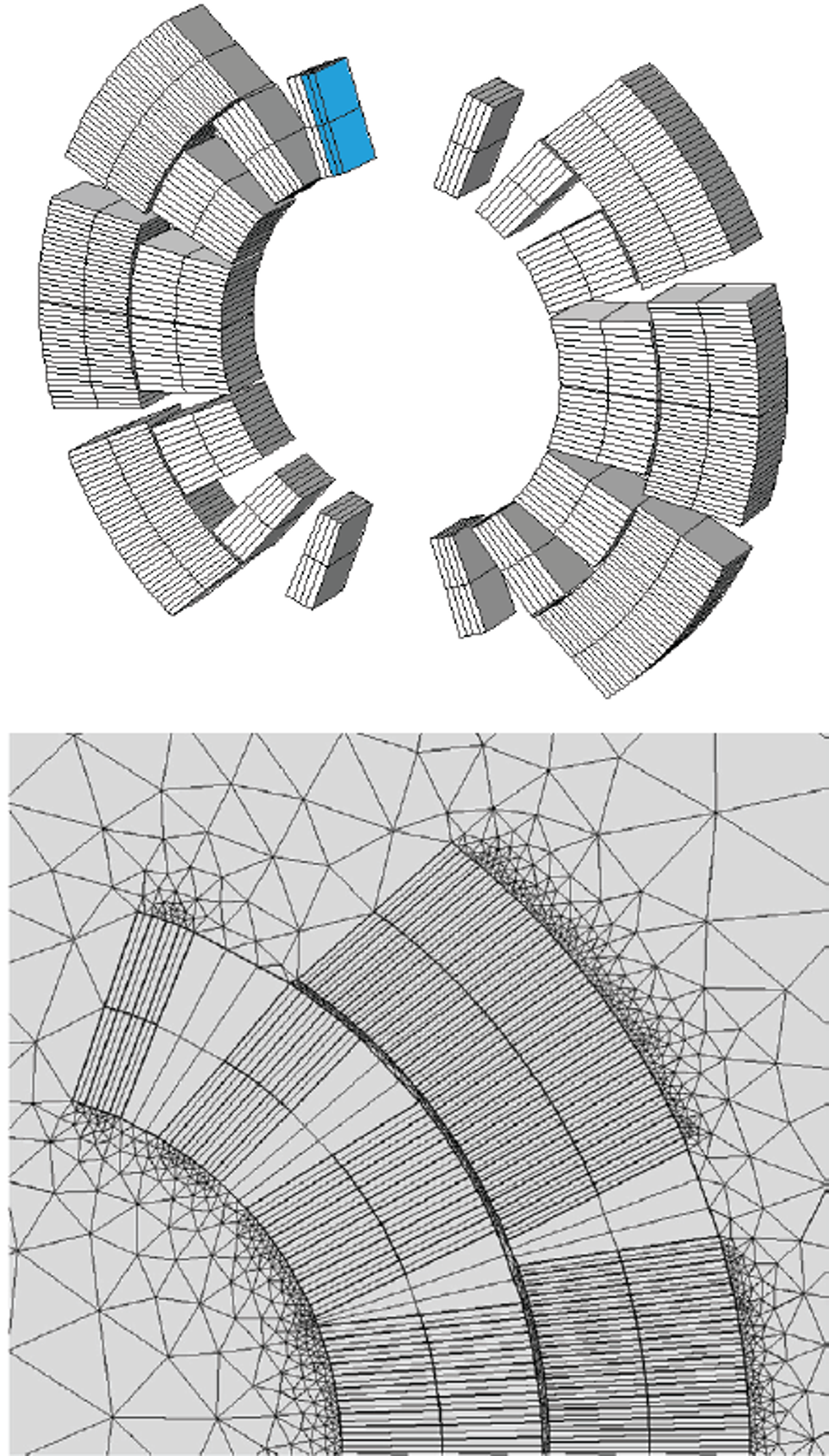 Figure 6. Top: Geometry of the magnet sections. Bottom: Mesh of the finite element model of the magnet sections.
Representing the electrodynamics and thermal evolution of a quench event involves modeling behavior on the scale of both meters (due to the size of the magnet cross section) and micrometers (due to the small diameter of the filaments within the cable). Furthermore, the quench is initiated in only a few microseconds and propagates in the order of milliseconds, while the complete discharge of the magnet can take up to one second. The team needed to study three very different timescales simultaneously.
“This problem is multiphysics, multiscale, and multirate,” Bortot explained. “Interdependent phenomena develop at different spatial and temporal scales.”
Most simulation software lacks the power to set up the model in a computationally efficient way and would necessitate a mesh covering six orders of magnitude and a solver time step fixed by the fastest time scale, creating an extraordinary amount of data and unreasonable computation time.
To circumvent this issue, the team at CERN implemented an expression for equivalent magnetization to analyze the system in the COMSOL® software (Figure 7). Instead of resolving the micrometric scale paths of the coupling currents occurring in the superconducting cable, they modeled such parasitic currents through their equivalent effect on the resulting magnetic field. “We implemented a formulation where we have an equivalent magnetization that is proportional to the derivative of the field through a time constant,” says Bortot. “This is a combination of Faraday-Neumann-Lenz and Ampère- Maxwell’s laws blended together. We could do this because we know the path the coupling currents will take in the cable and so we could associate an equivalent time constant.”
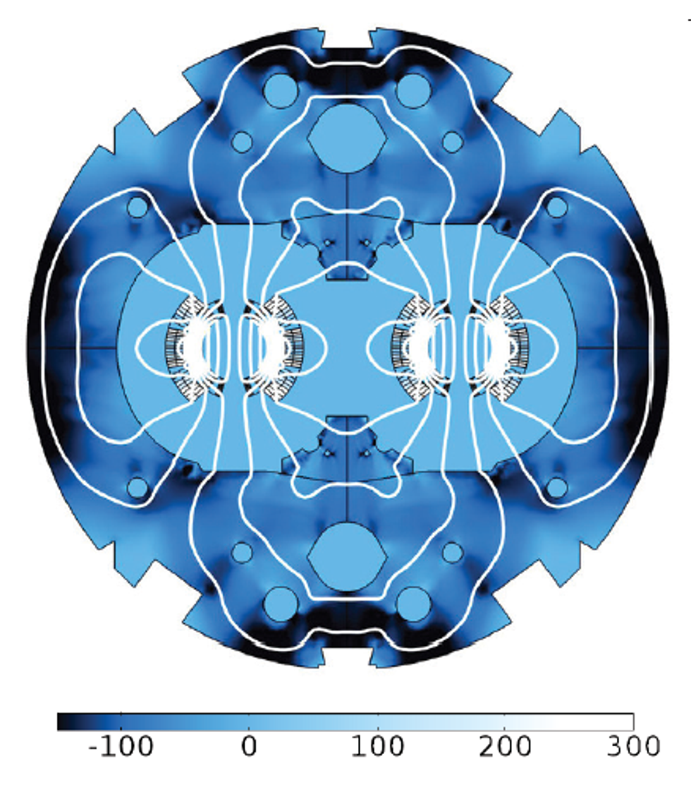 Figure 7. Equivalent magnetization of the eddy currents (A/m) during a linear ramp-up of 100 A/s at 8 kA.
Bortot also took advantage of the flexibility COMSOL offers to edit the standard Maxwell equations and change the variables. “Being able to edit the equations COMSOL solves, I could modify the standard vector potential formulation for my needs. Moreover, it was imperative that we have access to the previous solution time step because we needed the field derivative.
“Since we were already considering the coupling currents in the equivalent magnetization, we didn’t want any more currents circulating — they were already embedded. I disabled the induced currents over the coil domain and this simplified a lot of work. This was, I would say, the keystone of the whole architecture.” By not directly modeling the coupling currents, they were also able to significantly simplify the mesh (Figure 6, bottom).
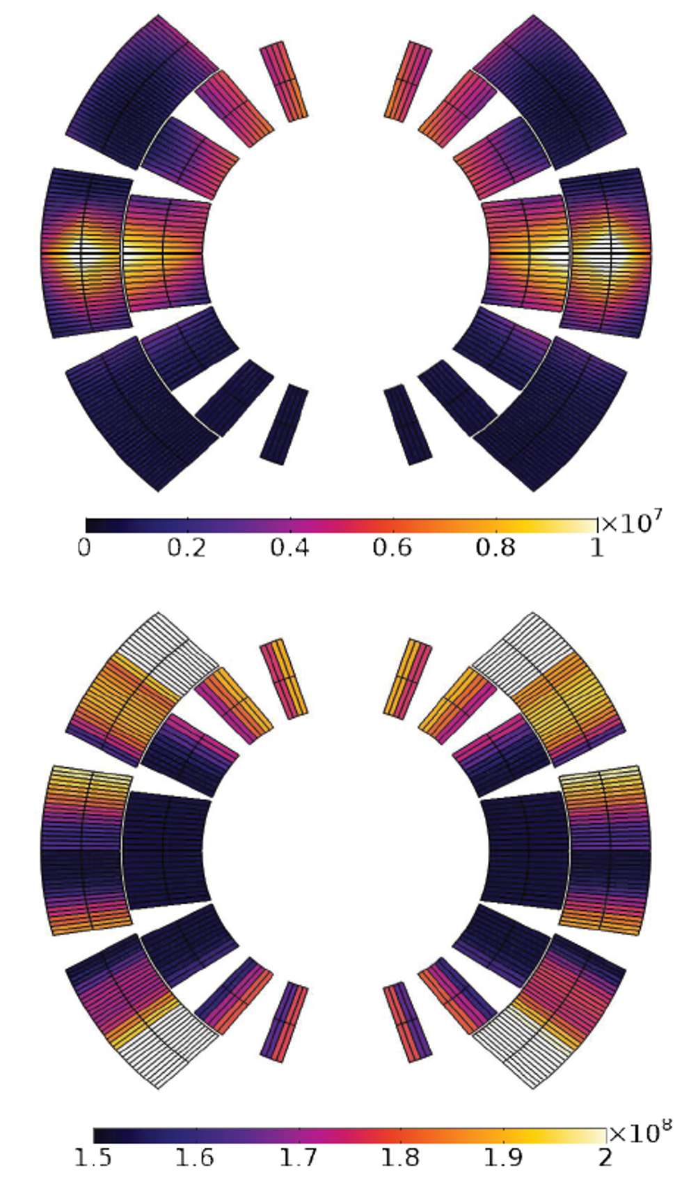 Figure 8. Different losses mechanisms in the coil, in W/m3. Top: CLIQ-induced eddy current losses. Bottom: Ohmic losses due to the spread of the quench.
In addition to the consistent modeling of the physics of the system, the practical construction of the model itself represents its own challenge. At cryogenic temperatures, the highly nonlinear material properties manifest as complicated numerical structures that are efficiently implemented and managed via external C functions, arranged in a shared, common library. Moreover, each half-turn needs to be characterized with both its related set of variables and operators and its micrometric insulation coating. The latter is critical for correctly capturing the quench propagation, and it is modeled with the built-in thin layer feature, that prevents an explicit mesh.
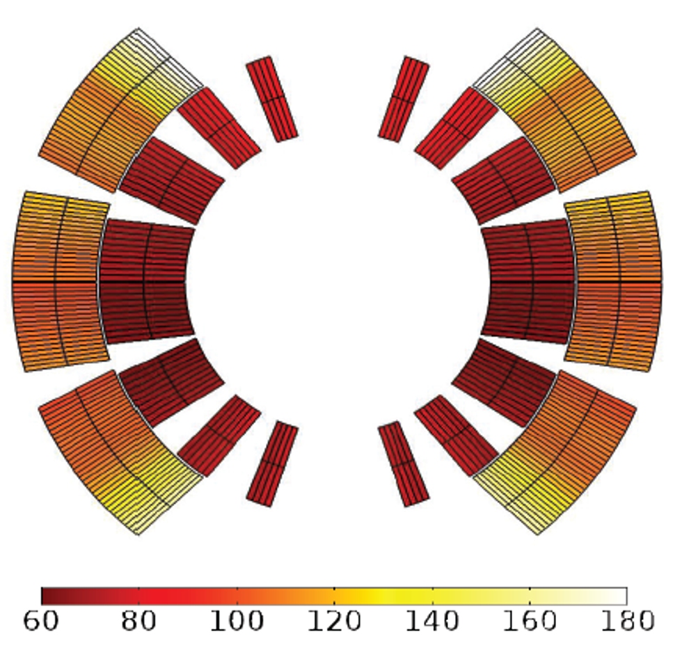 Figure 9. Temperature distribution (K) in the coil after a 500 ms quench event.
The assembly of these repetitive subunits is automated to be time-efficient and reduce the likelihood of human error. For this reason, the FEM model of the magnet’s cross section is created by a Java routine that transforms a user’s input into a distributed model, relying on the Application Programming Interface (API) provided by COMSOL. This guarantees that the FEM approach has the flexibility to adapt to different magnet types.
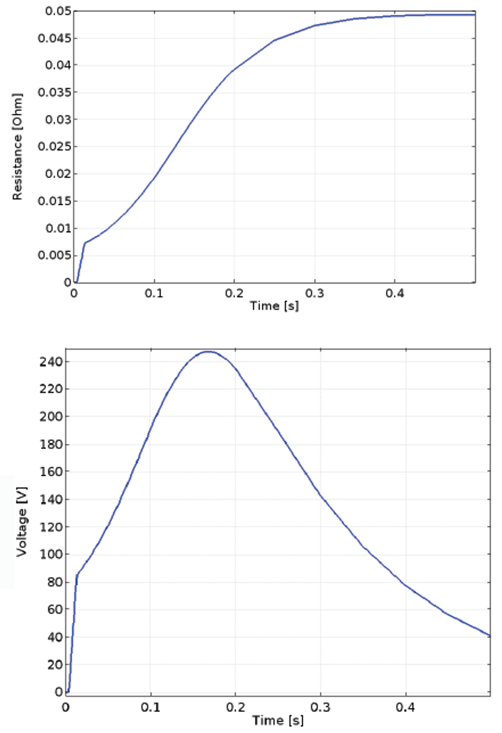 Figure 10. The COMSOL® software model results during a quench. Top: Growth of the Ohmic resistance in the coil. Bottom: Voltage signal extracted at the coil’s terminals.
Modeling the coupling currents as an equivalent magnetization allowed them to calculate losses immediately and express them as a function of the magnetic field variation. The team concluded that a variation of the magnetic field is directly dissipated as equivalent coupling current losses.
One of the main achievements was a simulation of a quench event in the LHC main dipole, assuming the sudden activation of the CLIQ protection system for the mitigation of the quench consequences. The analysis, which accounts for nonlinear temperature- and magnetic field-dependent material properties, investigated the oscillations in the magnetic field and the induced eddy and coupling current losses (Figure 8, top) in the superconductor; the spread of the quench and the resulting resistive heating (Figure 8, bottom); and the final temperature distribution due to the thermal loss deposition in the coil (Figure 9). By solving the heat balance equation, the design of the CLIQ unit was also cross-checked confirming the proper temperature was obtained in order to spread thequench throughout the magnet, ensuring that the right level of power was injected into the coil. The model furthermore allowed for the extraction of quench-related lumped parameters such as the coil resistance and voltage over time (Figure 10), to be used as further input for circuital models simulating the magnet’s external electrical network.
FROM THE LHC TO THE ACCELERATORS OF THE FUTURE
From Bortot’s simulation results, it was possible to reproduce the interconnected physics phenomena involved in the sudden energy dissipation, providing an analysis tool suitable for the deep investigation of magnet quench phenomena.
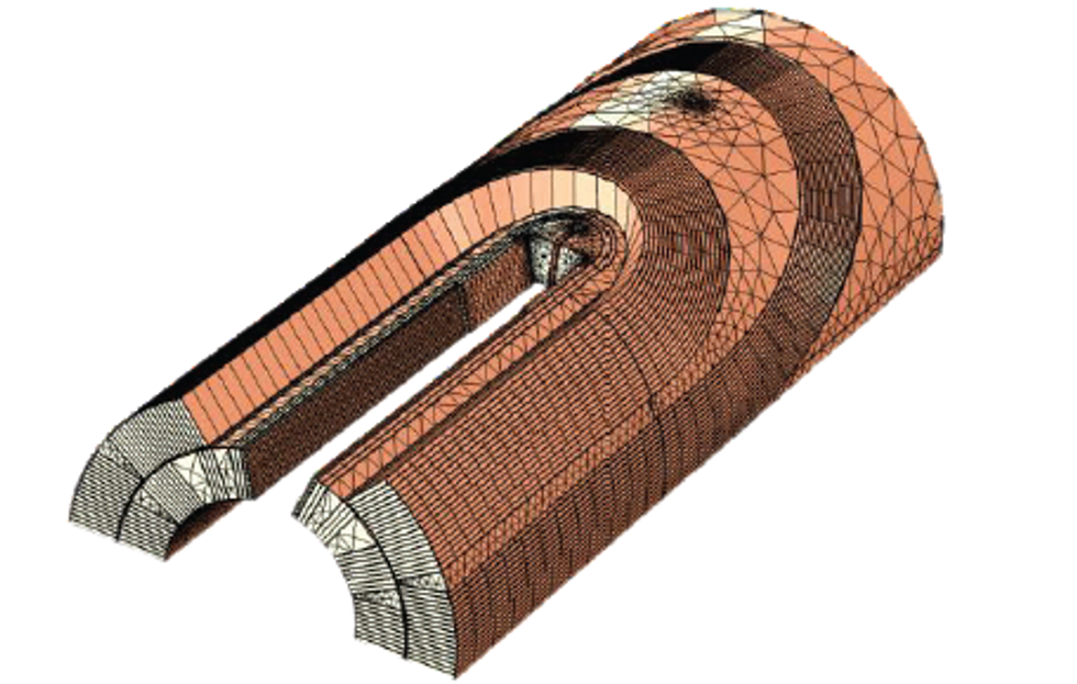 Figure 11. Proposed geometry and mesh for a future 3D model
The models are now being extended to the magnets currently under design and construction for the High Luminosity upgrade for LHC and for the Future Circular Collider project, the next-generation accelerator. The feasibility of extending the models to the 3D domain will also be explored (Figure 11). Running in parallel to the design process, the models will support and contribute to the development of the future quench detection and protection systems. The team’s contribution will help in protecting current and future accelerators from the consequences of quenches, allowing researchers to continue their investigations into the nature of matter without fear of damage to the superconducting magnets.
Click hereto read the 2017 edition of Multiphysics Simulation and learn how mathematical modeling and multiphysics simulation are being leveraged as a powerful tool in many other industries.