This sponsored article is brought to you by COMSOL.
Just as tourists in Paris are drawn to the Louvre, visitors to Stuttgart, Germany, also flock to museums displaying the great works of the city. Stuttgart may not boast of Degas or Monet, but its prominent names are perhaps even more famous than Paris’ painters: Mercedes–Benz and Porsche. Each of these iconic automakers maintains a museum in the southwestern German city they call home. Their gleaming galleries feature many historic and influential cars, almost all of them powered by petroleum-fueled internal combustion (IC) engines. Looking ahead, Stuttgart will likely continue to be the heart of the German auto industry, but how long will the IC engine remain the heart of the automobile?
Even the most successful manufacturers must adapt to changing conditions. The German automotive sector, along with its global counterparts, is doing so by developing elektrische autos. Electric cars are an important focus of Robert Bosch — another leading automotive company founded in Stuttgart. Today, Bosch supplies electric powertrains, systems, and components to automakers worldwide.
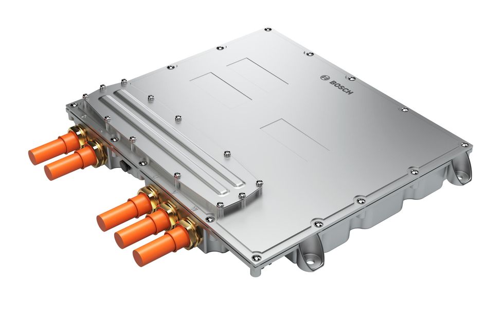
Figure 1. A Bosch three-phase inverter for automotive drivetrains.
As the automotive industry races toward an electrified future, Bosch is accelerating its R&D into the essential building blocks of electric drivetrains. One of these components is the inverter, which changes direct current (DC) from the car’s batteries into alternating current (AC) to power its drive motor (Figure 1). The inverter’s ability to provide a smooth flow of current depends on its integral DC link capacitor (Figure 2). “The capacitor is one of the most expensive components of the inverter. Its performance has a direct impact on the performance and reliability of the inverter, which is fundamental to the operation of the drivetrain,” explains Martin Kessler, Bosch senior expert for automotive electronics.
For the global automotive sector to meet its ambitious electrification goals, inverters and their capacitors must undergo continuous improvement and optimization. Martin Kessler and his team rely on multiphysics simulation to test and refine Bosch’s DC link capacitors. Their simulation-enabled predictive analysis complements and optimizes the live prototyping of new designs. “It is simply not possible to predict potential problems with testing alone; we need both simulation and prototyping working hand in hand,” says Kessler.
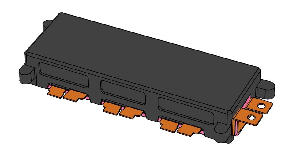
Figure 2. A typical DC link capacitor, with a battery interface on the right and transistor connectors on the front.
The Emerging Era of the Electric Automobile
“Drivers, start your engines!” As if heeding the call to begin a worldwide race, people everywhere begin their days by firing up a rumbling IC engine. But this familiar sound can seem ominous, especially as the environmental impact of vehicle emissions grows more apparent. To lessen these emissions and their contribution to global climate change, the automobile industry is ramping up the production of electric-powered cars and trucks. Many of the electric vehicles available today have familiar brand names, but under the hood, these cars often rely on the technology and expertise of outside suppliers.
It is worth noting just how significant a shift this is for a major global industry. Leading automakers are some of the world’s largest employers, and a vast share of their workers, R&D, and production capacity is dedicated to producing IC engines. The centrality of internal combustion to these companies can be found in their names, from General Motors to Bayerische Motoren Werke (better known as BMW). Why would companies known for their engines turn to outsiders to make their cars go? Perhaps it is because, in a sense, electrification is forcing the industry to learn how to produce an entirely different type of machine.
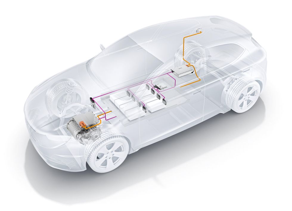
Figure 3. A Bosch schematic that helps explain the operation of a generic electric drivetrain. The amber line traces the path of drive current through the system, from the right to the left side of the picture. The path begins with a charger-converter, which accepts power from an external connection to the AC electrical grid. The charger-converter supplies DC to the battery, shown at the center of the car. The battery provides DC to a three-phase inverter, shown at the front of the car, mounted above the drive motor assembly. The inverter converts DC into three-phase AC to power the car's drive motor.
Anatomy of an Electric Drivetrain
To make a fully electric car, it is not enough to replace the engine with an electric motor and the gas tank with a battery. Such familiar devices are only parts of a larger system, which helps deliver smooth, reliable performance by adjusting to the constantly varying conditions under which every vehicle must operate (Figure 3).
Indispensable Inverter, Crucial Capacitor
The role of the inverter in an automotive drivetrain is simple in concept, but complex in practice. The inverter must satisfy the AC demands of the motor with the DC provided by the battery, but it must also adjust to ongoing fluctuations in load, charge, temperature, and other factors that can affect the behavior of each part of the system. All of this must occur within tight cost and spatial constraints, and the component must sustain this performance for years to come.
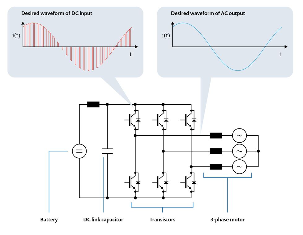
Figure 4. A diagram of a Bosch three-phase inverter’s core circuitry. The battery provides DC, which is converted to a three-phase AC by the action of three sets of transistors. By switching on and off in a precise sequence, the transistors produce alternating current in three distinct phases, causing the car’s drive motor to rotate. To make the motor's performance as smooth as possible, the DC link capacitor helps manage the input current that is fed to the transistors.
To understand the inverter’s function, consider what a three-phase AC motor needs in order to operate. If connected to DC, the motor simply will not rotate. Instead, it must be provided with alternating current with three distinct but complementary waveforms, enabling the motor’s three-part field coil to magnetically attract the segments of its rotor in a sequential pattern. “To control the activity of the motor, we must control the amplitude and frequency of the inverter’s current output,” explains Kessler. “The speed of the motor is proportional to frequency, while amplitude helps determine its torque.”
“The desired current waveform through the transistors has a relatively steep gradient. The only way to achieve switch-mode current with this high gradient is to have very low inductance in the source path,” Kessler says. Inductance is the particular force opposing changes in current flow. Every slight change in current will be limited by an induced counteracting voltage, which will disrupt the desired waveform — and the smooth rotation of the motor.
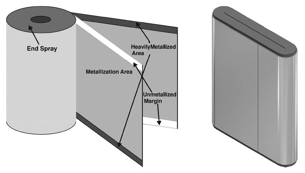
Figure 5. DC link capacitors are made from metallized polypropylene film, which is wound into an elongated canister shape.
To reduce the inductance in the source path of the transistors, a capacitor is placed in parallel across the input lead from the battery, which is called the DC link. The DC link capacitor (Figure 5) is placed in direct proximity to the transistors and provides the desired current waveforms through the transistors. The low impedance of the capacitor minimizes any remaining ripple voltage on the battery side.
A typical capacitor consists of two electrodes separated by an insulating gap, which may simply be airspace or some kind of material. In this application, Bosch uses capacitors made with metallized polypropylene film. A thin coating of metal (forming the electrodes) is sprayed on each side of the film, which provides the necessary dielectric gap. The metallized film is then wound tightly into a canister shape. As with the inverter itself, the capacitor’s conceptual simplicity conceals a multifaceted engineering design problem.
Challenges with DC Link Capacitor Design for Vehicle Inverters
Capacitors are widely available components that are installed in countless electronic devices. For the past seven years, Martin Kessler has been responsible for DC link capacitor design at Bosch. He has been with the company since 1989 and has worked on electric car technology since 2010. That such an experienced engineer is dedicated to this one component shows its importance — and its complexity.
“Why can we not just pick up a capacitor from the marketplace?” asks Kessler, rhetorically. “There are multiple interdependent factors at work. First, we have high demands for performance and reliability. Second, there are very tight spatial requirements. Third, we face difficult thermal constraints, as the polypropylene film in a capacitor can only withstand temperatures up to around 105°C. This issue is compounded by the interaction of electromagnetic and thermal activity throughout the inverter. And finally, the capacitor is relatively expensive,” Kessler explains.
Simulation (Not Luck) Helps Solve the Black Box Problem
To meet the design challenges of a DC link capacitor, Kessler developed a process that combines experimental testing with multiphysics simulation. As an example of why simulation-based analysis is a necessary part of his work, he cites the difficulty of finding and measuring potential hot spots, where high heat and coupled effects can cause failures. “We try to locate hot spots by placing a lot of thermocouples inside prototypes and measuring temperatures at various load points,” Kessler says. “But my mantra is that you will never find a hot spot like this without a lot of luck! You will need to be lucky to place the thermocouple in the right position,” he laughs.
“A simple 2D model of a capacitor is also insufficient,” Kessler continues. “The inverter is a distributed system with internal resonances and a complex loss distribution. Our coupled EM and thermal analysis must account for skin effects and proximity effects. We cannot calculate an absolute value for peak temperatures without a 3D finite element approach, which also enables us to model the spatial distribution of coupled EM and thermal effects. This is an ideal task for the COMSOL Multiphysics software,” Kessler says. (Figures 6–7)
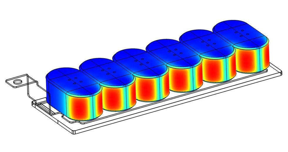
Figure 6. 3D model image showing simulation of EM effects inside a DC link capacitor design.
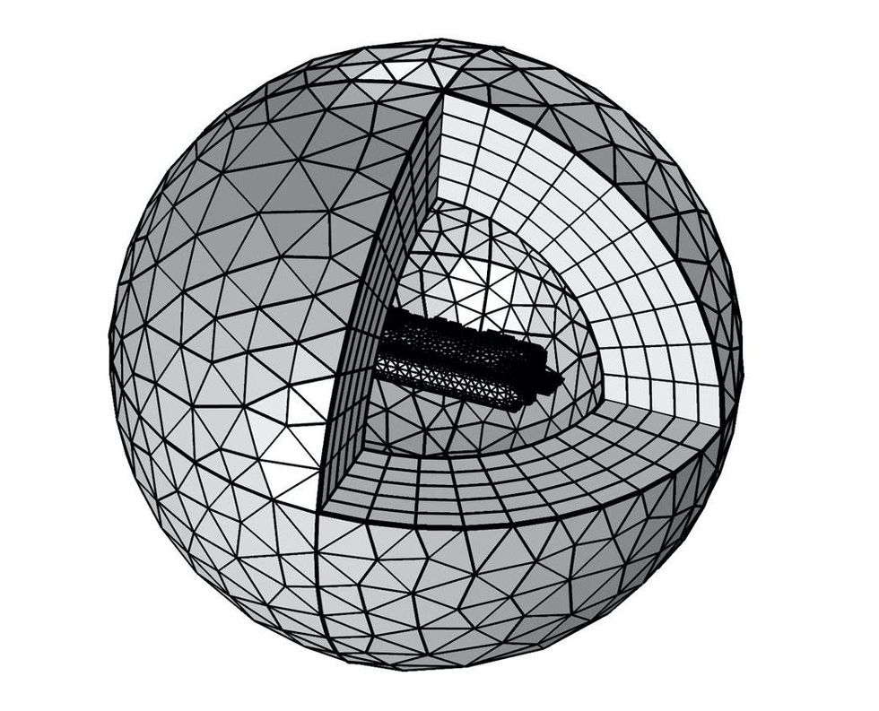
Figure 7. A model of the electromagnetic field generated by the capacitor, which aids the calculation of loss distribution in the unit.
Kessler’s design process validates simulation models against measured results, where possible, and then uses the validated models to pinpoint potential problems (Figure 8). “By helping us locate hot spots in the model, the simulation helps us avoid issues that would have appeared late in the development process, or even after production had started,” says Kessler. “Instead, we can get specific results and make adjustments early in the process.”
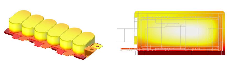
Figure 8. A 3D model showing simulation of thermal effects inside a DC link capacitor design, and a cutaway view showing the hotspot location in the capacitor.
“We perform EM modeling and validation of every new design. We compare the calculated equivalent series resistance (ESR) curve with the ESR curve as measured from a prototype (Figure 9). If these curves are aligned, we can set up boundary conditions for stationary and transient heat calculations,” says Kessler. “We can compare the temperature curves from our thermocouples with the results of probes in the COMSOL Multiphysics model. If they match, we can then simulate all the critical points where we must keep temperatures within limits.” The curve data is put into the COMSOL Multiphysics software via the LiveLink for MATLAB interfacing product.
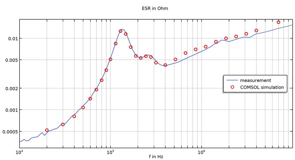
Figure 9. A plot of the ESR curve, as calculated in the simulation, compared with ESR values derived from measurement of a live prototype. Alignment of these curves helps validate the model for further analysis.
“Before we can do this, we have to think about which factors should be incorporated into the model,” says Kessler. “Some of the variables we receive from the OEM, such as maximum DC link voltage, are not very relevant to our simulation,” he continues. “But the current, switching frequency, e-machine values, and modulation schemes all help define a current spectrum. We need to calculate the current spectrum for all three phases of our output in order to establish power losses. Once we have this, we can do the harmonic analysis with COMSOL Multiphysics for the frequencies of the current spectrum. Then we sum up our losses for every harmonic,” Kessler explains.
Other important values include the boundary conditions, which help Kessler and his team determine coupled effects. “We calculate parasitic inductance of the capacitor with the AC/DC Module,” Kessler says. “We also find the complete AC loss distribution through the capacitor windings or internal busbar. Then we can couple the results and determine a temperature-dependent resistivity of the cover parts with the Heat Transfer Module,” he says. “This enables us to establish the maximum element hot spot temperature resulting from the EM activity.”
Findings from their analyses can then lead to design changes. Kessler explains that each new capacitor design typically undergoes three rounds of testing. “With simulation, the improvement curve gradient is much steeper from one phase to the next. Our knowledge grows quickly, and this is reflected in the final product.” The latest generation of Bosch inverters promises 6 percent greater range and a 200 percent jump in power density compared to previous designs.
Electrification Shifts into High Gear
As automakers convert more of their product lines to electric propulsion, Martin Kessler believes that the need for rapid, cost-conscious R&D will also increase. “Electric mobility is growing up now,” he says. “We expect that the OEMs will come to us with more varied needs, for inverters in different power classes and that meet tighter spatial constraints,” says Kessler. “I do think that the number of products that require new capacitor designs will keep expanding. With our simulation-driven development methods, we are confident that we can keep up with this growth.”
In the years to come, perhaps visitors to Stuttgart’s car museums will stop to admire the historic motors and inverters that powered the industry into a new electric age.
MATLAB is a registered trademark of The MathWorks, Inc.