The Conversation (0)

Illustration: John MacNeill
One morning in November 2014, Kamal Oudrhiri, a colleague of mine at the Jet Propulsion Laboratory (JPL), in Pasadena, Calif., burst into my office with an intriguing proposition. A first-of-its-kind satellite was headed for Mars. The satellite would fly alongside NASA’s InSight Mars Lander, relaying data in real time back to Earth during the lander’s critical entry, descent, and landing. “We have to achieve 8 kilobits per second, and we’re limited in terms of power. Our only hope is a large antenna,” Oudrhiri explained. “Oh, and the satellite itself will be only about the size of a briefcase.”
Nothing as diminutive as the Mars satellite—which belongs to a class called CubeSats—had ever gone farther than low Earth orbit. The antenna would be stowed during launch, occupying only about 830 cubic centimeters. Shortly thereafter, it would unfurl to a size three times as large as the satellite itself. It would have to survive the 160-million-kilometer flight to the Red Planet, including the intense vibration of launch and the radiation and extreme temperatures of deep space. How hard could that be?
Fortunately, my colleagues and I love a challenge, and we welcomed the chance to push CubeSat technology to its limits. These tiny spacecraft have become the go-to vessel for researchers and startups doing Earth imaging and monitoring. Compared with traditional satellites, they are relatively inexpensive and small, weighing just a few kilograms, and they can be ready to launch in a matter of months, rather than the years it typically takes to prepare a standard spacecraft. Over time, the onboard sensors and processing that CubeSats can carry have been the beneficiaries of Moore’s Law advancements in electronics, growing more powerful and sophisticated, lighter in weight, and energy efficient.
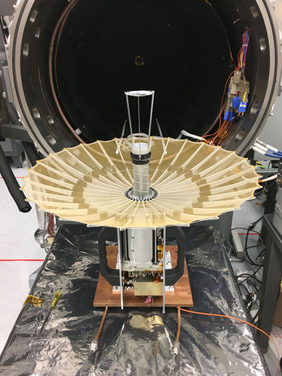 RainCube's Umbrella: The radar antenna for the tiny RainCube satellite folds up into a 10-by-10-by-15-centimeter canister. Upon deployment, its 30 ribs extend like an umbrella to form a parabolic dish that's still small enough to test in a thermal vacuum chamber.Photo: JPL/NASA
But a CubeSat’s small size can be a huge liability when it comes to communications. In particular, it’s been too difficult to outfit the satellites with antennas big enough to achieve high data rates or high-resolution radar. And so the tiny satellites have been limited to Earth orbit, unable to advance the scientific frontier beyond the immediate environs of our own planet. If we could somehow figure out a way to equip a CubeSat with a powerful high-gain antenna, vast new opportunities for research and exploration would open up. Earth-orbiting CubeSats could finally start doing radar-based science, such as measuring wind and precipitation. And with high-data-rate antennas, CubeSats could venture out and explore the solar system.
After a couple of years of dedicated effort, the antenna team at JPL finally solved the problem—and in two different ways. In one project, called Radar in a CubeSat (or RainCube), we designed a deployable antenna that will fan out like an umbrella once the satellite reaches orbit. In another project, called Mars Cube One (MarCO) and due for launch in May, we created a flat antenna that unfolds from the surface of the CubeSat. Our success has led NASA to start considering these tiny platforms for missions that were once thought possible only with a large, conventional satellite. Our antenna technology has also been patented and licensed to several commercial space companies. Here’s how we pulled off an engineering feat that many considered too hard and what we learned in the process.
CubeSats aren’t the only tiny satellites around, but they are the most adaptable and have received the widest attention. The basic building block is a cube that’s 10 centimeters on a side and weighs a little over a kilogram at most. From there, such “one unit” or “1U” cubes can be joined together as necessary; common variations are built from 3, 6, or 12 cubes.
Engineers at Stanford University and California Polytechnic State University initially developed CubeSats in 1999 as a way to introduce students to the hands-on process of designing, fabricating, launching, and operating a satellite. Since then, a large variety of CubeSat subsystems have been fielded, and they’ve become versatile tools for specialized missions.
Best of all, they are quick to assemble. At JPL we’ve gone from formulation to delivering the finished design to the assembly and test facility in 10 to 12 months, instead of the three or more years it would take for a larger, less modular spacecraft.
Of course, a conventional satellite weighing thousands of kilograms can carry many more instruments than a tiny CubeSat can. But for a mission with a specific goal, CubeSats can be a cheap and attractive option. What’s more, launching constellations of CubeSats will boost the spacecraft’s temporal resolution, allowing them to remotely sense the same area more frequently than a larger spacecraft could. With some help from our new antennas, RainCube’s and MarCO’s missions are not only feasible but eminently sensible.
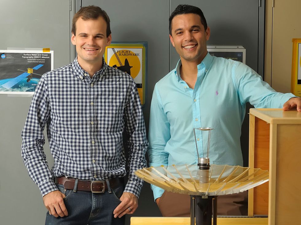 Antenna Engineers: The Jet Propulsion Laboratory team that developed the RainCube antenna included Jonathan Sauder (in checked shirt) and Nacer E. Chahat.Photo: JPL/NASA
As its name suggests, RainCube is built to watch the weather. Its radar will help NASA study precipitation and improve weather-forecasting models. NASA scientists are planning to launch a constellation of such satellites to achieve better temporal resolution than a single large satellite can provide.
This tiny radar craft is only about the size of a cereal box (“6U” in CubeSat parlance). The power system, the computer, the control system, and everything else must fit into that box. And like any box of cereal, it needs room for a prize: the radar. Through some ingenious engineering, RainCube’s principal investigator, Eva Peral, managed to simplify the radar instrumentation and shrink it by an order of magnitude. Still, by the time everything else had been crammed in, only one-fourth of the space was left for the radar and its antenna.
The satellite will send and receive radar signals through a parabolic antenna. The main dish will reflect the signals onto a device called a subreflector, which will channel them into a “feedhorn” and from there into the satellite’s radar circuitry. At an altitude of 450 to 500 km, RainCube’s radar will survey the clouds it’s flying over, and so it requires a half-meter-wide antenna to achieve a 10-km-wide radar footprint. Prior to being deployed, however, that antenna needs to fold up into a canister measuring 10 by 10 by 15 cm. And the 35.75-gigahertz frequency at which the radar operates means that the reflector must deploy so precisely that its shape deviates from perfection by no more than 200 micrometers.
Clearly, we had some tough design challenges to overcome. After some intense brainstorming, the RainCube antenna team—which consisted of Jonathan Sauder, Mark Thomson, Richard Hodges, Yahya Rahmat-Samii, and me—settled on an antenna that works a bit like an umbrella stuffed into a jack-in-the-box. This approach was the simplest solution, given the volume available.
When an umbrella opens, the ribs extend outward and stretch the fabric until it’s taut. RainCube’s antenna works the same way: During deployment, a series of ribs pull the antenna into the right shape to transmit and receive signals.
Video: JPL/NASA
The precision and the accuracy of that shape are dictated by the number of ribs. If we used just three ribs, the absolute minimum, it would create a three-sided pyramid, while an infinite number of ribs would in theory create a perfectly accurate parabolic surface. But adding more ribs also increases the chance of things going wrong during deployment.
We eventually determined that 30 was the optimal number of ribs for RainCube. That’s enough ribs to provide a sufficiently accurate surface while keeping the risk of deployment failure acceptably small. To further improve the overall accuracy of the radar antenna system, the engineers designed the subreflector to account for the shape of the 30-rib antenna—including its minute deviations from the ideal—and to focus the radar properly. This tuning of the subreflector boosts the antenna’s efficiency by 6 percent, which translates into a 12 percent improvement in the radar’s signal-to-noise ratio.
It wasn’t just the antenna’s shape that had to be rethought. In a deployable structure, coaxial cable is the common choice to get radio-frequency signals from a feedhorn into the body of a satellite. But at the Ka-band frequencies that RainCube will use, a cable would lose too much of the signal. So JPL engineers designed a waveguide feed—consisting of a hollow metal tube through which the signals propagate—that will remain in place while the rest of the antenna slides along it and unfolds.
RainCube’s umbrella design was clever, but space is a challenging environment for any electromechanical system. The antenna will endure intense vibrations during launch as well as huge temperature variations in orbit—typically –20 °C to 85 °C for internal components—as the CubeSat moves in and out of Earth’s shadow. Up there, a failure in even a minor component can scrub an entire mission, as NASA engineers know all too well.
RainCube’s antenna has obvious similarities to the 18-rib high-gain antenna on the Galileo probe, which failed to deploy in 1991. But we had an advantage here. Unlike Galileo’s 4.8-meter-wide antenna, RainCube’s is small enough to test inside a vacuum chamber, so we were able to run trials in all conditions. And indeed, after the first vibration test, one of the ribs didn’t deploy, which the team traced to a design flaw in a single spring. After we redesigned this part, the antenna passed all its tests. It’s now ready for launch, which could happen as soon as this May. A successful mission will be a watershed event, opening the way for entire constellations of CubeSats carrying scientific experiments into Earth orbit.
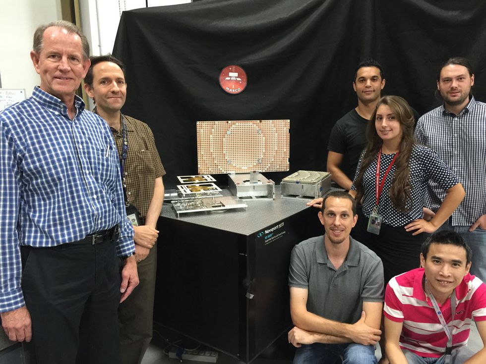
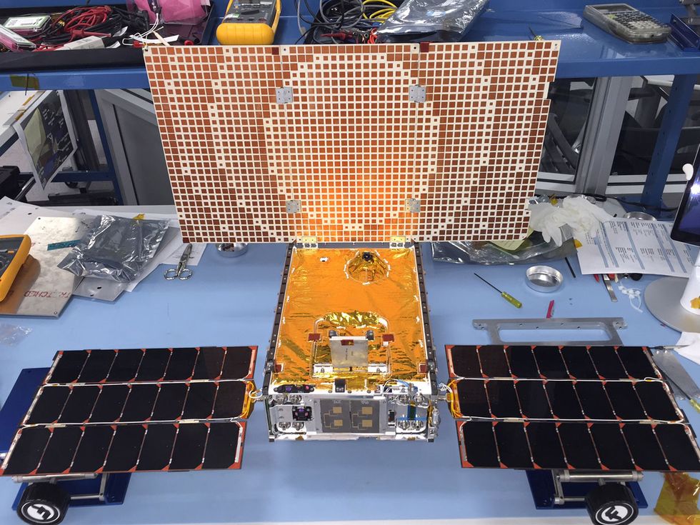 Messages From Mars: The twin MarCO CubeSats (bottom) will launch this May to Mars, where they’ll send data from the InSight lander back to Earth, 160 million kilometers away. The satellites use a flat antenna called a reflectarray, the surface of which is patterned to mimic a parabolic dish, concentrating signals toward Earth. The MarCO antenna team (top) includes (from left) Richard Hodges, Joseph Vacchione, Phillip Walkemeyer, the author, Savannah Velasco, Vinh Bach, and Emmanuel Decrossas.Photos: JPL/NASA
It’s hard to imagine something as tiny and intricate as a CubeSat surviving the void of interplanetary space. Nevertheless, that’s what we expect two briefcase-size CubeSats to do this year. The twin Mars Cube One (MarCO) CubeSats will be the first to travel into deep space, flying with NASA’s InSight lander when it launches in May. Arriving at the Red Planet in November, these CubeSats will help provide real-time communication between the lander and NASA’s Deep Space Network here on Earth. They’ll be working alongside the Mars Reconnaissance Orbiter (MRO), which has been orbiting the planet since 2006.
The MarCO CubeSats are designed to receive data from InSight’s entry, descent, and landing using a deployable UHF loop antenna. Each satellite’s software-defined radio will then retransmit the data at a higher X-band frequency for the 160-million-km trip across interplanetary space back to Earth. One of the Deep Space Network antennas, which each measure 70 meters across, will receive the data. Given the limited RF output power of the CubeSat radio, the tiny satellite’s antenna needs an aperture of 33.5 by 60 cm to establish a reliable radio link at 8 kilobits per second.
Ideally, the MarCO CubeSats would have parabolic antennas like RainCube’s, but there just isn’t room. The team was given only 4 percent of the spacecraft payload’s volume to work with, and our solution had to weigh less than a kilogram. As if that weren’t daunting enough, we were confined to using just one side of the CubeSat. MarCO’s tight schedule—nine months from the beginning of antenna development to integration on the spacecraft—meant that we didn’t have time to design custom parts. So we needed a simple design that relied on off-the-shelf parts wherever possible.
We created a flat antenna, called a reflectarray, which consists of a three-part panel that flips out from the side of the spacecraft and opens under the power of spring-loaded hinges. As the panel flips away from the body of the spacecraft, the antenna feedhorn also pops up, rotating around an off-the-shelf connector. We dotted the antenna’s flat surface with a reflective pattern so that it can mimic a parabolic antenna and concentrate signals in the direction of Earth.
When the MarCOs launch, they will likely carry the first reflectarrays into deep space. If the mission succeeds, we could see more such CubeSats fulfilling similar roles. Right now, for instance, data from Mars rovers and landers is relayed back to Earth via larger spacecraft such as the MRO. Future CubeSats could go into orbit around Mars and help relay that data, at a much lower cost.
The antennas that RainCube and MarCO will use can do much more than what’s called for in their specific missions. Indeed, our team is already working on larger deployable antennas based on the same principles. Next up is the One Meter Reflectarray (OMERA) antenna, which is a square reflectarray that measures 1 meter on a side. We believe such an antenna could be used for deep-space communications as well as higher-resolution RainCube-like orbiters.
It’s an exciting era for CubeSats and other small satellites, and there is much more to come. Exploration Mission 1, the first planned flight of NASA’s replacement for the space shuttle, will carry 13 CubeSat missions. Some will visit the moon, others will depart for deep space, but all of these tiny spacecraft will have one thing in common: small antennas capable of supporting big science.
This article appears in the February 2018 print magazine as “A Mighty Antenna From a Tiny CubeSat Grows.”
About the Author
Nacer E. Chahat is a senior engineer at the Jet Propulsion Laboratory, in Pasadena, Calif.


