

The satellite industry could experience its biggest revolution since it joined the ranks of commerce, thanks to some of the smallest machines in existence. Researchers are performing experiments designed to convince the aerospace industry that microelectromechanical systems (MEMS) could open the door to low-cost, high-reliability, mass-produced satellites.
MEMS combine conventional semiconductor electronics with beams, gears, levers, switches, accelerometers, diaphragms, microfluidic thrusters, and heat controllers, all of them microscopic in size [see "A Quick Glance at MEMS"]. "We can do a whole new array of things with MEMS that cannot be done any other way," said Henry Helvajian, a senior scientist with Aerospace Corp., a nonprofit aerospace research and development organization in El Segundo, Calif.
All satellites require a basic set of subsystems to do useful work in orbit [see figure]. A power source is one, typically a solar cell array backed up with batteries. Also necessary are a communications system to receive commands and return information, internal sensors to gauge the satellite's state, and a control unit to coordinate all subsystem activities. Satellites with more complex missions will also require systems to determine the spacecraft's orientation and position and propulsion systems to control both.

If all the functions of these subsystems can be performed by MEMS, then "you could start thinking of fabricating satellite subsystems like we make CMOS chips for laptops," said Helvajian. Satellites could be constructed by stacking wafers covered with MEMS and electrical components. The result would be a "1-kg-class satellite, or picosat, that could be mass produced...you could put up a constellation of hundreds of these little guys in low Earth-orbit [LEO] and get, say, incredible weather information," he continued.
The same was said by Thomas George, who supervises the MEMS Technology Group, part of the Jet Propulsion Laboratory (JPL), in Pasadena, Calif. Such satellites, having negligible mass, size, and power consumption requirements, can be easily piggybacked on conventional satellites or launched using smaller and cheaper launch vehicles, he told IEEE Spectrum.
Some of the advantages of using MEMS-based satellites were spelled out by Ernest Robinson, a distinguished engineer at Aerospace. Low launch costs and high resistance to radiation and vibration headed the list. It costs about US $10 000/kg to put an object into LEO. Clearly, smaller, lighter satellites will cost less to launch. MEMS-based satellites also promise to be cheaper to develop and fabricate than conventional spacecraft.
Robustness is also key. "You can't upset a MEMS switch with a single cosmic ray impact, but you can upset a semiconductor switch by doing that," Robinson explained. This means that MEMS are much more resistant to radiation damage and so would be "able to operate comfortably in a very high-radiation environment such as the Van Allen belts." The Van Allen belts occupy a region of space between LEO and the crowded geosynchronous orbit. Potentially a valuable piece of orbital real estate, it has remained relatively unexploited because of the practical and economic difficulties of shielding conventional satellites from high doses of radiation.
Then there's MEMS resistance to high levels of vibration and the shock of, say, a rocket launch. George referred to a demonstration by Honeywell Corp., of Morristown, N.J., of an imaging array of MEMS-based bolometers (bolometers are used to detect infrared and microwave radiation). The array was tested on the Earth's surface by being shot from a howitzer. Though subjected to accelerations estimated at 20 000 times gravitational acceleration, the bolometers worked perfectly afterward.
The reason MEMS devices stand up to these kinds of forces so much better than conventionally sized devices is clear: the mass of each moving component is extremely small, so that potentially damaging internal forces between components are also very small.
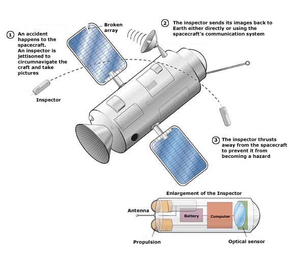
An inspector on board
All the same, the first application of MEMS-based miniature spacecraft will most likely not be as an independent long-lived satellite or satellite constellation, but as a short-lived inspector device. An inspector would consist of a battery, a control computer, a small propulsion unit, and some optics or other sensors, such as an infrared detector. It would communicate wirelessly with its mothership [see figure].
When a spacecraft malfunctions, a great deal of time and energy is spent doing detective work to find out what happened and ascertain its current state. Yet much of this effort could be short-circuited if even a picture or two of the spacecraft were available to ground controllers, thanks to an inspector.
"Inspectors could play an important role during the construction and operation of the International Space Station. Such a large structure is bound to degrade over time...external inspection will be a necessity," said Craig Underwood, a senior lecturer at the Surrey Space Center of the University of Surrey, in Guildford, Britain. Spacecraft could carry one or two of the roughly 250-gram disposable inspectors, which would lie dormant until needed. If an anomaly occurred, they would be dispatched to reconnoiter.
Underwood is also the chief architect of the SNAP-1 satellite built by Surrey Satellite Technology Ltd., an offshoot of the university. (The acronym stands for Surrey Nanosatellite Applications Platform.) SNAP-1 was launched in June 2000 alongside a second satellite aboard a Russian rocket. While the miniaturized design did not use MEMS technology, its mission was to validate the inspector concept.
"We were able to use SNAP-1 to observe the deployment of [the second satellite] and the video telemetry allowed us to more accurately determine the separation dynamics," Underwood told Spectrum. Surrey Satellite intends to use MEMS technology in future small satellites.
Proving program
It won't happen right away. There is a long way to go before all satellite functions can be duplicated by MEMS-based components.
"The greatest challenge faced by picosats is the same one faced by all MEMS technology: how to maintain a high degree of capability under severe constraints of mass, size, and power," said JPL's George. "We need to accumulate a wealth of hard engineering data to prove that MEMS devices can cut it in space." Each subsystem must be demonstrated in practice.
To this end, Robinson has begun an ambitious satellite development program involving a sequence of component-proving missions. Apparently, it started almost by accident. Initially, the researchers simply wanted to send aloft some experimental MEMS switches designed for switching RF signals. They soon realized, though, that the experiment was best not mounted on a conventional spacecraft. "If you become part of a larger system, there are all kinds of integration issues," Spectrum was told by Robinson. "We recognized the way to prove MEMS was to come up with an independent miniature test platform."
Robinson went to the U.S. Defense Advanced Research Projects Agency (DARPA) and obtained funding for Aerospace to build two test picosats, put them as passengers on board another research satellite, the orbiting picosatellite automated launcher (OPAL) operated by Stanford University, in California, and launch them into orbit from space.
"This is not a big program--we're talking about a few hundred thousand [dollars], not millions--[but] a preliminary flight to establish the test infrastructure," said Robinson. "The experiment itself was driven by the technical maturity of the MEMS available." In fact, his program of building toward a fully functional MEMS-based satellite is paced by the development programs of other MEMS researchers and manufacturers.
"We're taking the steps as the technology is available," explained Robinson. "When you go to the various contractors who have been researching MEMS and ask for something that has actually been moved out of the laboratory into something you can use in a space system, it's amazing how little you find." The satellites themselves take little time to design and build, with the first pair of satellites funded and constructed in about eight months.
The picosats weighed less than 280 grams apiece and comprised little more than a small radio derived from digital cordless telephone technology, two patch antennas, batteries, and an array of experimental RF MEMS switches to be tested. RF switches switch an antenna between transmit and receive modes. The MEMS variety are faster, draw less power, and have lower signal losses than conventional equivalents. The switches on board the picosats were not used to control any of the satellite's own systems.
OPAL was launched in January 2000 and the picosats were ejected a week later. The satellites performed well, successfully communicating independently with the ground and proving their ability to test MEMS devices in space. By the time they were launched, Robinson was already prepared with another pair of satellites carrying a next-generation version of the switches.
Good timing
While Aerospace was building the first pair, the Air Force Research Laboratory, headquartered at Wright Patterson Air Force Base in Ohio, visited the company to solicit a replacement experiment for an upcoming launch of the service's MightySat 2.1 research satellite (one of the original experiments had been removed). "I called my sponsor at DARPA and asked for another $175 000 to have another flight," recalled Robinson. MightySat was launched in July of last year and the picosats have sat on board it since. This pair is planned to be ejected next month.
Having them wait in orbit for over a year is deliberate. The idea is to demonstrate the feasibility of the inspector concept, namely, that these devices can lie dormant out in space for long periods of time yet operate on demand.
The next step for Aerospace is to fly MEMS subsystems aboard picosats as functional components, not just test devices. The next flight will use RF switches to switch the antennas between receive and transmit modes--and also to test MEMS-based gyros.
Gyros are of assistance in determining a spacecraft's orientation in space--a critical function. Traditionally, spinning gyroscopes maintain a fixed frame of reference, but in the MEMS-based type, three pairs of rate sensors and accelerometers are mounted perpendicular to each other in order to monitor the spacecraft's movements [see "How to Model and Simulate Microgyroscope Systems," IEEE Spectrum, June 1998, pp. 66-75 ].
But the drift rate of MEMS gyros is an issue, said Surrey Satellite's Underwood. While less of a problem for short-lived inspector-style missions, a poor drift rate would badly affect the navigational ability of longer-lived MEMS-based satellites. A possible solution is to use the global positioning system (GPS) network to periodically recalibrate the gyros.
After that, MEMS-based optical elements, such as miniature cameras and infrared sensors, are to be introduced to begin actual imaging, followed by a microfluidic system for basic propulsion. Here, small tanks etched into a layer of silicon and sealed with another layer of silicon would hold small quantities of propellant. Microfluidic channels would guide the fluid to a nozzle, where it would be accelerated to provide thrust. Among the approaches suggested are: vibrating membranes; a gas turbine 1 cm in diameter; and electrically accelerating ionized propellants.
MEMS valves leak, though, and with such minute propellant amounts involved, even quite low leak rates can soon leave a satellite out of fuel. Despite these challenges, "hopefully, by about six flights from now, we'll be able to demonstrate complete functionality of an inspector," said Robinson. In other words, in two or three years.
Different strokes
MEMS satellite subsystems are often very different from their conventional counterparts, as the gyros show. Take the propulsion and thermal control systems, two of the most important under development.
Thermal control is especially important for satellites in LEO, with orbital periods ranging from 60 to 100 minutes, with maybe half of that time in direct sunlight and the other half in Earth's shadow, depending on the precise orbit. External temperatures fluctuate widely, so the satellite must prevent itself from being alternately baked and frozen. With conventional satellites, thermal shielding and heat flow pipes can solve the problem, while their sheer bulk increases the satellites' thermal inertia and insulates components against rapid changes in temperature. But something weighing only hundreds of grams needs a different approach.
For short-lived missions, insulation is sufficient. On the test picosats already flown by Aerospace's Robinson, the connection to the external antennas is a very long coiled wire to provide thermal isolation between the antenna and the electronics. The electronic boards and the MEMS array are isolated from the aluminum housing by plastic holders that are also tortuously shaped, to increase the path length the heat must travel.
Longer-lived satellites will require more complex systems. One approach would be to cover the surface of the satellite with tiny louvers [see figure ]. The louvers resemble the micromirrors developed for displays by Texas Instruments Inc. They would be supported by a hinge and a stop pillar above a silicon surface, their lids aluminized to reflect heat and light and the silicon coated with a high-emissivity material. When heat needs to be dumped, louvers facing away from the sun are opened by twisting their hinges electrostatically to expose the high-emissivity coating. As silicon is transparent to infrared radiation, a heat source below the coating would radiate infrared through it into space and so cool down. Also, channels can be etched in a silicon surface and covered with a thin film to create miniature heat pipes. Methanol can be pumped along these pipes to transfer heat from one portion of the satellite to another.

It all depends on attitude
Satellites need propulsion systems for two purposes: to move from one orbit to another, and for attitude control. A satellite that cannot control its orientation toward the sun will soon lose power from its solar cells, while a satellite that cannot orient its communication antennas toward ground stations or other spacecraft is useless. Generally speaking, once a satellite has reached its desired orbit, attitude control is the primary function of its propulsion system.
A MEMS-based digital thruster for attitude control is under development by Aerospace, TRW Inc. (headquartered in Cleveland, Ohio), and the California Institute of Technology, in Pasadena. The thruster is composed of a silicon wafer covered with a grid of tiny, single-use cells containing explosives. The wafer is placed on the outer surface of the picosat. When detonated by a small electrical heater element, each cell produces a small, standard burst of thrust. Different patterns of cells are fired to produce different amounts of uniform thrust around the wafer axis and to use the wafer as fully as possible. In future versions, once all the useable cells are fired, the wafer may be jettisoned to expose a fresh wafer stacked underneath [see figure].
Uses for the digital thruster will exist even on larger, conventional satellites. Larger satellites often have large photovoltaic solar cell arrays to meet their power needs. When deployed, these arrays tend to wag back and forth, so that the entire satellite oscillates. "But with these one-shot thrusters, we'd be able to dampen the noise," said Aerospace scientist Helvajian. The wagging would be measured using MEMS-based accelerometers, and a central control unit would calculate which thrusters to fire to neutralize the motion. Digital thrusters have already been tested as part of the payload of a sounding rocket (one that follows a suborbital flight path into or above the upper atmosphere). During the March launch from White Sands, N.M., 29 of the 30 miniature thrusters aboard test-fired successfully.
For larger orbital maneuvers, microelectric propulsion systems can be used. Electric propulsion systems use electrical fields to accelerate the heavy metal ions exhausted from the spacecraft, pushing it in the opposite direction. They are very efficient, but provide low amounts of thrust. Larger spacecraft can use them only on lengthy missions, such as interplanetary expeditions, where velocity can be allowed to build up over weeks. But a 1-kg satellite requires a mere 1-10 millinewtons of thrust, making electric propulsion a viable option for quick maneuvers.
The small size of these satellites also means that, relative to their total bulk, the area collecting solar power is much larger than on conventional craft. This gives the propulsion system a much better electric power-to-weight ratio.
Unique challenges
In addition, the space environment poses a set of challenges not faced by conventional satellites or by MEMS devices on the ground. Some MEMS devices, such as miniature motors or resonators, are electrostatically activated. If one is exposed in orbit to a lot of ionizing radiation, charge can build up and prevent correct operation. So to dissipate excess charge, leakage paths must be built into any MEMS destined for space.
Packaging must not be overlooked, either. To prevent overheating, components must have a way to either conduct or radiate away excessive heat.
All this adds up to another MEMS satellite requirement: a new type of designer. Siegfried Janson, a senior scientist with Aerospace, said that for MEMS-based solid-state satellites weighing only a few kilograms, the real challenge is doing the mechanical designs and integrating them with the electronic designs on the silicon wafer level. "Most rocket scientists don't know how to design ICs and most IC designers know nothing about rockets--we have to bring the two worlds together," he told Spectrum.
If these hybrid designers can be found and if aerospace MEMS development makes steady progress, constellations of cheap satellites should be vastly enhancing communications and remote sensing within the next decade or two. Better yet, when something goes wrong with a probe in orbit around Mars or when a panel on a space station becomes loose, we should be able to send something out to have a look, thanks to these tiny mechanical machines. "We are only limited by our imagination in terms of the useful functions these satellites can perform," said George.
To Probe Further
For an in-depth look at how actuators, optical devices, micropumps, valves, and various chemical and physical sensors are being monolithically integrated with transistors to create new generations of powerful microsystems, see "The broad sweep of integrated microsystems," by S. Tom Picraux and Paul J. McWhorter, IEEE Spectrum, December 1998, pp. 24–33.
To find out more about micropropulsion devices, visit the Web site at https://www.design.caltech.edu/micropropulsion/index.html.